Pride Mobility Jazzy Select 7 User Manual
Page 26
26
www.pridemobility.com
Jazzy Select 7
Assembly
To assemble the power chair:
1. Place the three frame assemblies next to each other as shown in
figure 20.
2. Grasp the front frame and fit the notch on the front frame bottom
bar onto the locating pin on the lower section of the power base
frame assembly.
WARNING! The front frame should be positioned
with the two semicircular notches in the vertical
bar facing forward.
3. Pivot the front frame top bar toward the power base frame
assembly and push the front frame top bar onto the locking
mechanism until the two assemblies snap securely into place.
See figure 18.
4. Repeat steps 1-3 for the other power base frame assembly.
WARNING! Make certain that the front frame is
snapped securely to both the right frame
assembly and to the left frame assembly.
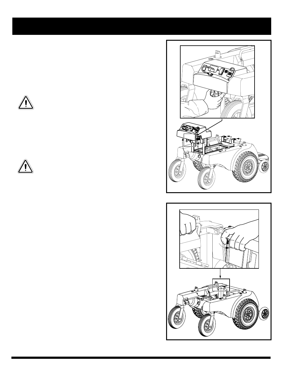
5. Hold the battery well frame so that the bottom of the well hangs
downward.
6. Position the notches on the front of the battery well frame onto
the locating pins on the front frame bottom bar. See figure 21.
7. Fit the notch on either side of the rear of the battery well frame
onto the locating pin on each power base frame assembly.
8. Make certain that the locking mechanisms snap securely into
place.
9. Reinstall the service disassembly bracket. See figure 17.
NOTE: The service disassembly bracket must be reinstalled
as the chair is reassembled after service.
10. Place the front battery box into the front end of the battery well
frame.
NOTE: Make certain that the connectors are facing toward
the center of the power chair.
11. Place the rear battery box into the back end of the battery well
frame. Make certain that none of the wiring harnesses or cables
are pinched between the battery or the motor controller box
and the frame.
12. Connect the battery boxes.Use the battery connection label
located on the back of the electronics tray for reference.
V . S E R V I C E
Figure 18. Removing Battery Well Frame
Figure 19. Power Base Frame Removal/
Installation