Patterson-Kelley MOD-04 User Manual
Page 9
Modu-Fire
®
Gas-Fired Boiler
Installation
6
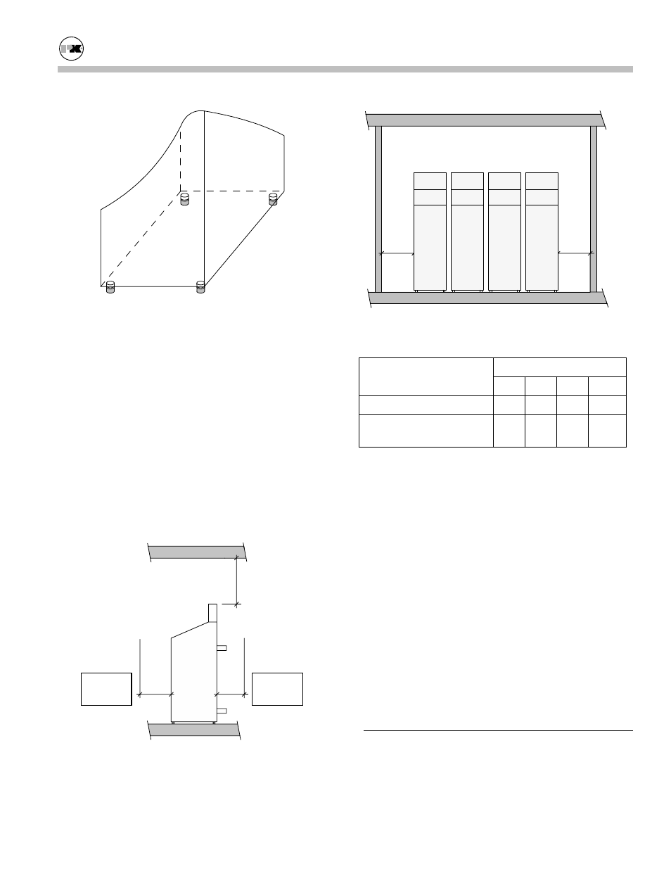
Adjustable Legs for Leveling and Floor Clearance
3.3.3 Clearances
If the boiler is to be installed near combustible sur-
faces, the minimum clearances shown in the table be-
low must be maintained.
Failure to provide for the service access clearances,
even with non-combustible surfaces, may cause future
problems servicing the boiler.
The boiler must be installed in a space large in com-
parison to the boiler as described in Section 6.3 of the
National Fuel Gas Code, ANSI Z223.1, latest edition.
A
B
C
No pipes,
ducts, etc.
in this area.
D
D
Minimum Clearances from Adjacent Walls, Ceiling, and
Obstructions
Dimensions (inches)
Type of Surface
A B C† D
Combustible
Surfaces
30 24 30 24
Non-combustible Sur-
faces
30 24* 30 24**
† "C" dimension includes clearance to remove the
burner. Do not put pipes, ducts, etc. in this area above
the boiler.
* CSA minimum. Actual clearance depends upon
stacking requirements.
** Service access need be only on one side of a boiler
or row of boilers. Boilers may be installed immedi-
ately adjacent to each other. However, P-K recom-
mends this clearance between each boiler when there
is insufficient access at the rear to allow for service
and adjustment.
In Canada: The boilers are approved for installation
with zero clearance to combustible surfaces, but 24
inch service clearances are recommended.
3.4
E
LECTRICAL
C
ONNECTIONS
All field wiring connections for power and control are
in the rear service panel on the back of the boiler.
Low voltage and high voltage terminal strips are indi-
cated on the wiring diagram. The boiler power circuit
Back of
Boiler
Front of
Boiler