Patterson-Kelley MOD-04 User Manual
Page 45
Modu-Fire
®
Gas-Fired Boiler
Parts/Technical Support
42
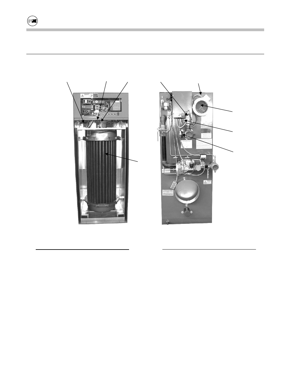
6.2
B
OILER
P
ARTS
L
IST
6.2.1 Main Assembly
No.
Part
1.
Mixer Core, Burner (Inside Cabinet)
2.
Burner Orifice (Inside Cabinet)
3.
Spark Igniter Electrode
4.
UV Scanner
5.
Thermowell w/Clamp
6.
Electrode Assembly w/Mica (Inside Cabi-
net)
7.
Pilot Tube (Inside Cabinet)
8.
Burner (Inside Cabinet)
9.
Heat Exchanger
10. Blower Damper
11. Pressure Relief Valve (100 PSI)
No.
Part
12.
Water Flow Switch
13.
Blower, Motor (Inside Cabinet)
14.
Blower, Wheel (Inside Cabinet)
15.
Press./Temp. Gauge
Installation/Owner’s Manual All Models-MOD
CP
Control Panel (Section 6.2.2)
EC
Exterior Cabinet (Section 6.2.4)
IC
Interior Cabinet (Section 6.2.4)
PG
Pilot Gas Train (Section 6.2.3)
MG Main Gas Train (Section 6.2.3)
5
4
3
11
13, 14.
9
10
12
15