Panasonic MN101C77C User Manual
Page 107
III - 13
Chapter 3 Interrupts
Overview
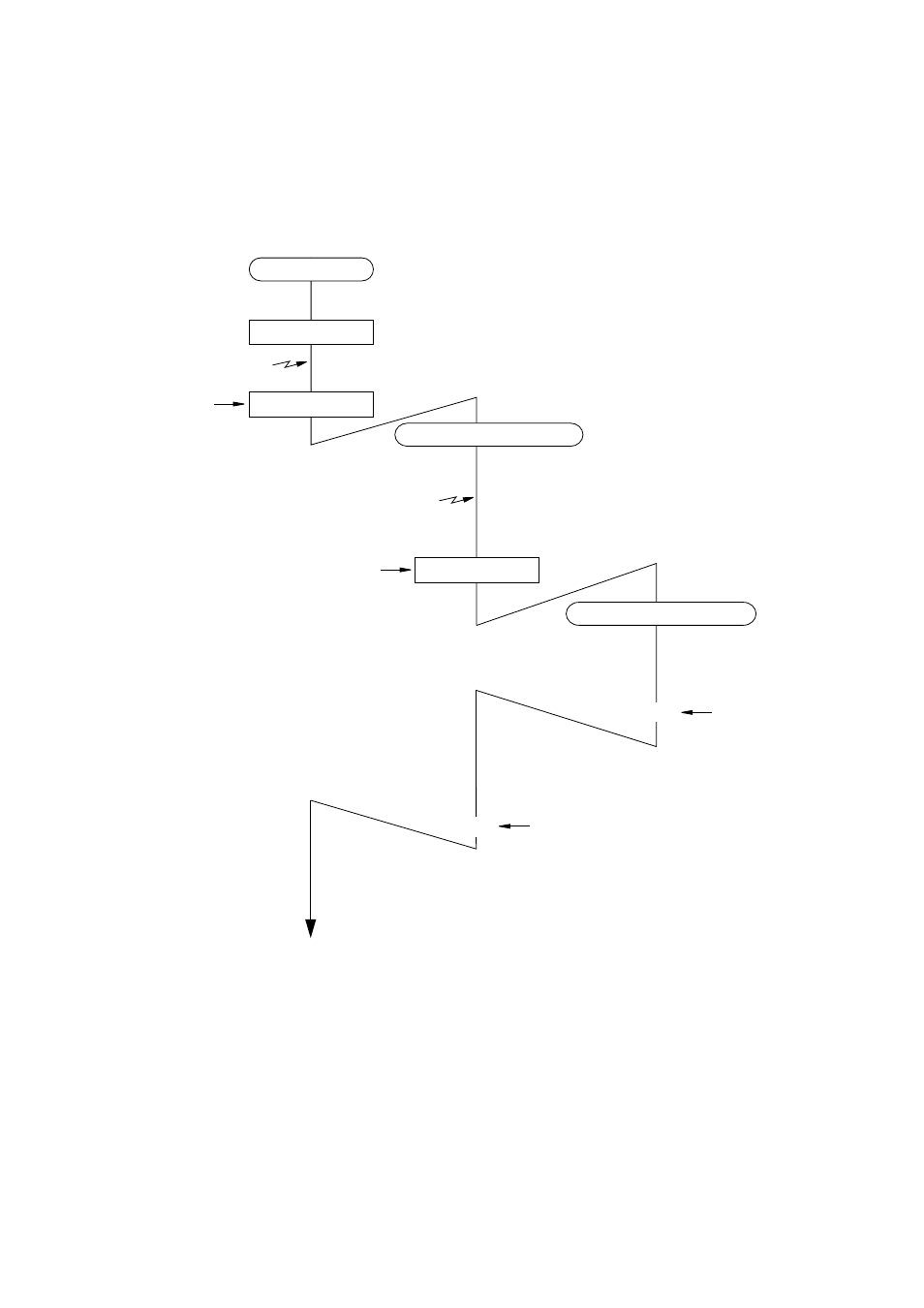
Figure 3-1-7 Processing Sequence with Multiple Interrupts Enabled
Interrupt 1 generated
(xxxLV1,0='10')
Main program
IM1,0='11'
Interrupt service routine: 1
RTI
(
IM1,0='10'
* Interrupt 2 generated
(xxxLV1,0='00')
)
Accepted because xxxLV1,0
Interrupt acceptance cycle IM1,0='00' ) ( IM1,0='11' ) ( ) ( Interrupt service routine: 2 IM1,0='10' RTI Accepted because xxxLV1,0 Restart interrupt processing program 1 Interrupt acceptance cycle Figure 3-1-7 shows the processing flow for multiple interrupts (interrupt 1: xxxLV1-xxxLV0='10', and interrupt 2: xxxLV1-xxxLV0='00'). Parentheses ( ) indicate hardware processing
This manual is related to the following products: