Patton electronic 1089/I User Manual
Page 9
(because it originates after the framer) and is
intended to be evaluated only by another
Processor. If the units are transmitting data and
the pattern generator is enabled on one end of
the link, the far end will begin receiving
unframed packets and assume that the line has
gone down. During test modes, the pattern gen-
erator is forced to time out before it can cause
the DSL link to go down.
Loop Control
This part of the Processor is used to control
Remote Loopback test mode. In a Remote
Loop, the 511/511/E data is looped back to the
line and to the remote unit over the DSL span.
15
Restart Procedure
The restart procedure is in place to allow the
and Time Outs
units to re-establish a connection after the
framer begins seeing unframed packets. The
Test Mode Timing Chart below shows the
amount of time the framer must see consecutive
unframed packets before the unit will restart and
try to establish a new line connection. The rea-
son that there are different Restart Times will
become apparent after reading the rest of the
document. The 511/511E Time Out shown refers
to the amount of time the 511/511E pattern will
be valid. At the end of this time the pattern will
automatically turn itself off and the normal data
path will be re-established. The ER led will flash
indicating to the user that the test has timed out.
The ER led will stop flashing once the 511/511E
switch is placed into the normal position.
Symbol Indicators
This symbol designates the origination or the
termination of a data path. The direction of the
arrow connected distinguish the two data paths.
This symbol designates an invalid data path. If
there is data present it should be ignored.
16
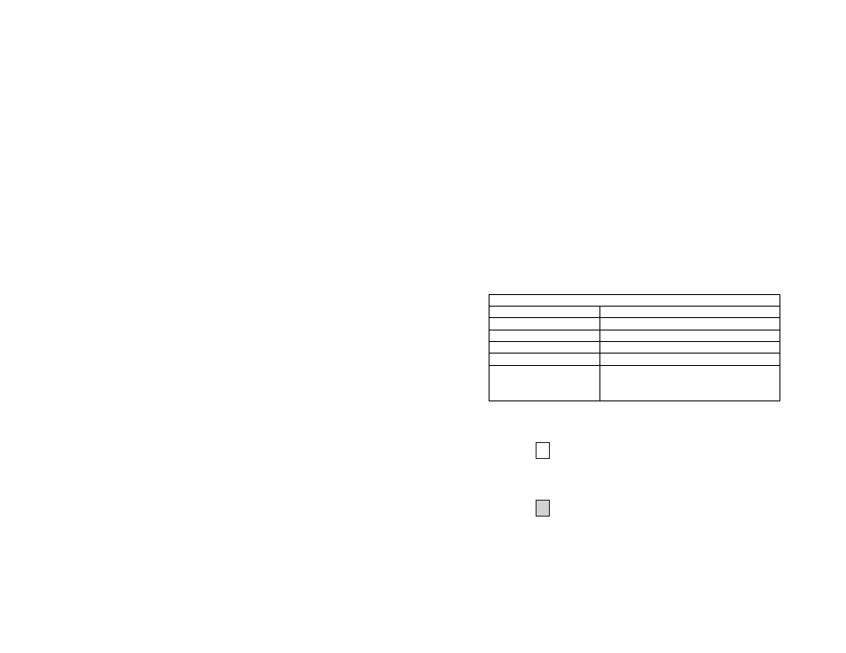
Test Mode Timing
Item
Elapsed Time (seconds)
Start Up
50
Data Mode
4
511/511E Generator Enabled 60 (The generator will stop after 45 seconds.)
Remote End of an RDL
60
511/511E Time Out
45 (The pattern generator will automatically turn
off after 45 seconds. The ER LED will flash until
the user turns off the 511/511E switch.)