Patton electronic 1089/I User Manual
Page 4
33..00 C
CO
ON
NFFIIG
GU
UR
RA
ATTIIO
ON
N
The Model 1089 has two sets of eight DIP switches, which allow
configuration for a wide variety of applications. This section describes
switch locations and explains all settings.
3.1 CONFIGURING THE HARDWARE DIP SWITCHES
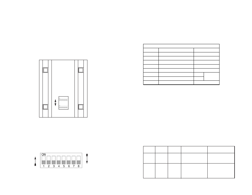
The 16 external switches are grouped into two eight-switch sets,
and are externally accessible from the underside of the Model 1089, as
shown in Figure 1, below).
The two sets of DIP switches on the underside of the Model 1089
will be referred to in this manual as S2 and S3. As Figure 2 shows,
the orientation of all DIP switches is the same with respect to “ON” and
“OFF” positions.
5
Figure 2. Close Up of Configuration Switches (all sets are identical in appearance)
3.1.1 Configuration DIP Switch Set “S2”
The only setting for S2 is for Clocking Mode between Model
1089s. All other switches are reserved for factory usage and must
remain in the default configuration. Default settings are shown in the
table below.
Switch S2-1, S2-2, S2-3, S2-4, S2-5 and S2-8:
Switches S2-1, S2-2, S2-3, S2-4, S2-5 and S2-8 are reserved for fac-
tory use and must remain in the factory default settings as shown in
the table above. .
Switches S2-6 and S2-7: Clock Mode
Use Switches S2-6 and S2-7 to configure internal, or receive
recover (clocking derived from the remote Model 1089 across the DSL
span) settings. One Model 1089 (typically the CO, or “Central Office”
unit) will be set for Internal Clock. The remote Model 1089 (typically
the CP, or Customer Premises unit) will be set for Receive Recover
clocking. The table below shows the clock mode settings.
6
Position
Function
S2-1
Reserved
S2-2
Reserved
S2-3
Reserved
S2-4
Reserved
S2-5
Reserved
S2-6
Clock Mode
On
S2-7
Clock Mode
Off
S2-8
Reserved
Off
Off
Off
Receive
Recover
Off
Off
Off
S2 SUMMARY TABLE
Factory Default
OFF
ON
FRONT
REAR
Figure 1. Underside of Model 1089 Series, showing location of DIP switches
S2
S3
ON
OFF
CO/CP
Unit
S2-6
S2-7
Clock Mode
Description
Model 1089 gener-
CO
On
On
Internal
ates internal, crys
tal controlled timing.
Model 1089
CP
On
Off
Receive Recover receives its timing
from the CO unit
over the DSL span.