Connectors, Pixel position – Planar LC640.480.33-AC User Manual
Page 18
LC640.480.33-AC Operations Manual (OM600-01)
16
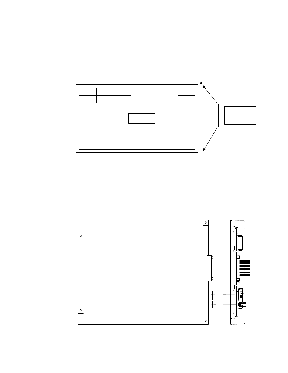
Pixel Position
The position of pixel data, relative to the color filter orientation and scan direction
inputs is shown in Figure 8. Refer to the timing diagrams in Figures 5, 6, and 7 for
horizontal pixel position (D1 through D640), and for vertical line position (DH1
through DH480).
Figure 8. Pixel position of input data (480-line mode).
D640,DH480
D640,DH1
D1,DH480
D1,DH1
D2,DH1
D3,DH1
D1,DH2
D2,DH2
D1,DH3
R
G
B
R/L=H
U/D=L
UP
The display image may be rotated 180 degrees using the R/L and U/D signals present
on J3. Refer to Inverting the Display on page 21 for more information.
Connectors
The LC640.480.33-AC display has three connectors on the side of the display. J3 is the
video connector, J2 is the dimming connector, and J1 is the backlight power connector.
Figure 9. Connector Locations.
J2
J1
J3