Planar LC640.480.33-AC User Manual
Page 13
LC640.480.33-AC Operations Manual (OM600-01)
11
Signal Timing
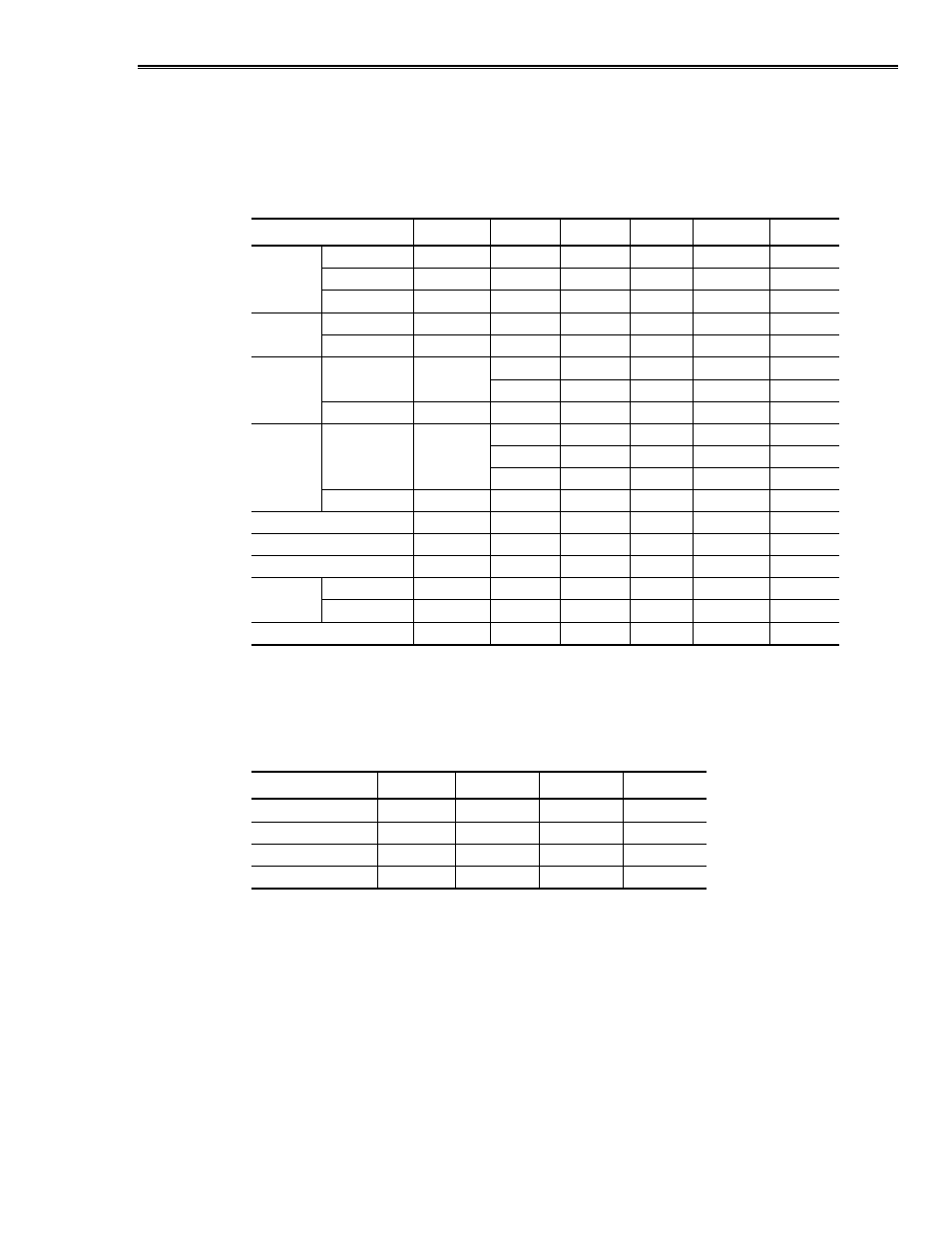
Video signal timing diagrams are shown in Figures 5, 6, and 7. The following table refers
to these diagrams.
Table 10. Video signal timing.
Parameter
Symbol
Mode
Min
Typ
Max
Units
Clock
freq
1/Tc
all
–
25.18
28.33
MHz
hi time
Tch
all
5
–
–
ns
lo time
Tcl
all
10
–
–
ns
Data
setup time
Tds
all
5
–
–
ns
hold time
Tdh
all
10
–
–
ns
Horiz.
cycle
TH
all
30.0
31.78
–
µ
s
sync
all
750
800
900
clock
PW
THp
all
2
96
200
clock
Vertical
cycle
TV
480
515
525
560
line
sync
400
446
449
480
line
350
447
449
510
line
PW
TVp
all
1
–
34
line
Horiz.display time
THd
all
640
640
640
clock
Horiz. to clock
THc
all
10
–
Tc-10
ns
Vsync to Hsync
TVh
all
0
–
TH-THp
clock
Enable
setup time
Tes
–
5
–
Tc-10
ns
hold time
Tep
–
2
640
640
clock
Hsync to Enable
THe
–
44
–
TH-664
clock
Table 11 below summarizes timing for the different vertical modes given typical vertical
sync “cycle” (TV) values. In this table, data for line TVn is displayed as the first top row
on the screen.
Table 11. Vertical mode video signal timing.
Mode
Symbol
480 line
400 line
350 line
V-data start
TVs
34
34
61
V-data period
TVd
480
400
350
V-display start
TVn
34
443-TV
445-TV
V-display period
–
480
480
480
The LC640.480.33-AC display timing is fundamentally the same as the Sharp
LQ10D421 display. Horizontal display position is determined by the rising edge of the
ENAB signal, and the ENAB signal has no relation to the vertical display position. If
ENAB is permanently low, display starts from the data at “C104” referred to in the
timing diagrams in Figures 5, 6, and 7. ENAB should not be left at a logic high
permanently. In 400 and 350 line modes, data should be at a logic low during the vertical
invalid period.