Part identification chart – ProForm Fusion PFSY6806.0 User Manual
Page 21
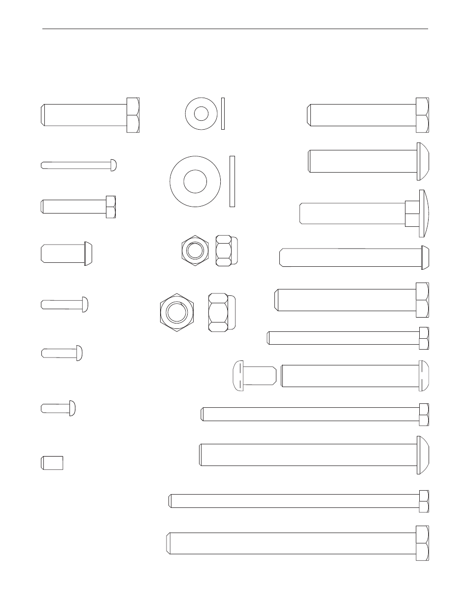
M6 Washer (107)
M10 Washer (105)
M8 Nylon Locknut (110)
M10 Nylon Locknut (108)
M10 x 55mm Carriage Bolt (83)
M8 x 20mm
Button Bolt (92)
M8 x 65mm Button Bolt (94)
M6 x 115mm Screw (113)
M6 x 70mm Screw (93)
M4 x 16mm
Self-tapping
Screw (99)
M4 x 19mm Self-
tapping Screw (100)
M4 x 13mm
Self-tapping
Screw (112)
M3 x 32mm Screw (102)
M10 x 50mm Button Bolt (88)
M10 x 100mm Button Bolt (91)
M10 x 115mm Bolt (84)
M10 x 65mm Bolt (95)
M10 x 50mm Bolt (96)
M10 x 40mm Screw (97)
M6 x 30mm Screw (87)
M6 x 10mm Set
Screw (114)
M6 x 100mm Screw (85)
2.5" Bolt Set (86)
PART IDENTIFICATION CHART
Refer to the drawings below to identify small parts used in assembly. The number in parentheses by each draw-
ing is the key number of the part, from the PART LIST in the center of this manual.
Note: Some small parts
may have been pre-attached. If a part is not in the parts bag, check to see if it has been pre-attached.
- 29633.1 (24 pages)
- 831.23744.1 (28 pages)
- 630DS 831.299254 (26 pages)
- PFB38030 (23 pages)
- 775 CT PFTL72707.0 (32 pages)
- PFBE64490 (22 pages)
- 831.288080 (16 pages)
- PFSY74490 (33 pages)
- 831.297980 (22 pages)
- 831.28622.0 (16 pages)
- StrideClimber 831.23745.0 (28 pages)
- PFSY69520 (33 pages)
- 495Pi PFTL33105.0 (22 pages)
- PFCG2224.0 (19 pages)
- 831.293230 (19 pages)
- PFEL7806.1 (28 pages)
- 831.299402 (18 pages)
- 730CS 831.299271 (26 pages)
- CrossTrainer PFTL54706.0 (32 pages)
- 6.0 GSX PFTL51105.3 (26 pages)
- PFCCEL39013 (24 pages)
- 831.293201 (30 pages)
- 750 PFTL73105.2 (30 pages)
- 831.298061 (18 pages)
- 831.299220 (18 pages)
- 530 PFTL51233 (34 pages)
- PFBE1416.0 (16 pages)
- PFEL5105.1 (24 pages)
- PCEL87076 (18 pages)
- 831.293060 (30 pages)
- 720 (30 pages)
- 831.29604.2 (30 pages)
- 600 N PFEL6026.0 (24 pages)
- GT 30 (16 pages)
- 580X 831.293063 (30 pages)
- 831.285735 (16 pages)
- PCEL87070 (18 pages)
- 831.288221 (12 pages)
- PFTL94105.0 (30 pages)
- PFEL54932 (24 pages)
- PFEL19540 (16 pages)
- PFTL98580 (22 pages)
- Interactive Ergometer PFEVEX62832 (32 pages)
- 831.297460 (22 pages)
- 831.299461 (26 pages)