Cable diagram, Weight resistance chart – ProForm Fusion PFSY6806.0 User Manual
Page 17
17
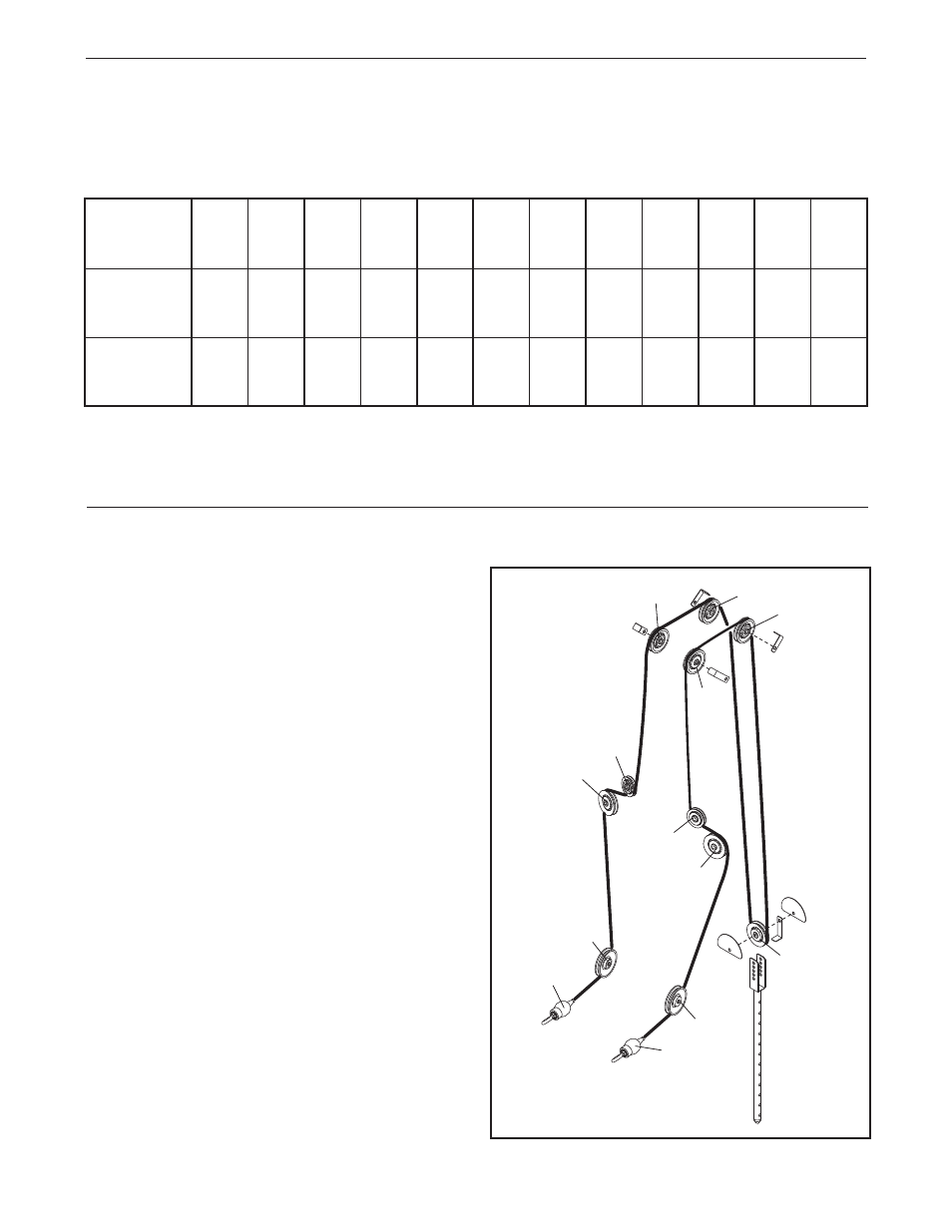
CABLE DIAGRAM
The cable diagram shows the proper routing of the
Press Arm Cable (66). Use the diagram to make sure
that the Cable and the cable traps have been assem-
bled correctly. If the Cable has not been correctly
routed, the weight system will not function properly
and damage may occur. The numbers show the cor-
rect route for the Cable.
Make sure that the cable
traps do not touch or bind the Cable.
13
6
7
9
2
10
4
5
Press Arm Cable (66)
1
12
3
11
8
WEIGHT RESISTANCE CHART
The chart below shows the approximate weight resistance for the 12.5 lb. weights.
Note: The actual resistance
at each station may vary due to differences in individual weight plates and friction between the cables,
pulleys, and weight guides.
*The weight resistance shown is for each arm.
WEIGHT
1
2
3
4
5
6
7
8
9
10
11
12
Press
Arm*
9
15
20
25
30
36
41
46
51
57
62
67
Leg
Developer
20
30
42
50
65
73
92
97
108
125
137
144
- 29633.1 (24 pages)
- 831.23744.1 (28 pages)
- 630DS 831.299254 (26 pages)
- PFB38030 (23 pages)
- 775 CT PFTL72707.0 (32 pages)
- PFBE64490 (22 pages)
- 831.288080 (16 pages)
- PFSY74490 (33 pages)
- 831.297980 (22 pages)
- 831.28622.0 (16 pages)
- StrideClimber 831.23745.0 (28 pages)
- PFSY69520 (33 pages)
- 495Pi PFTL33105.0 (22 pages)
- PFCG2224.0 (19 pages)
- 831.293230 (19 pages)
- PFEL7806.1 (28 pages)
- 831.299402 (18 pages)
- 730CS 831.299271 (26 pages)
- CrossTrainer PFTL54706.0 (32 pages)
- 6.0 GSX PFTL51105.3 (26 pages)
- PFCCEL39013 (24 pages)
- 831.293201 (30 pages)
- 750 PFTL73105.2 (30 pages)
- 831.298061 (18 pages)
- 831.299220 (18 pages)
- 530 PFTL51233 (34 pages)
- PFBE1416.0 (16 pages)
- PFEL5105.1 (24 pages)
- PCEL87076 (18 pages)
- 831.293060 (30 pages)
- 720 (30 pages)
- 831.29604.2 (30 pages)
- 600 N PFEL6026.0 (24 pages)
- GT 30 (16 pages)
- 580X 831.293063 (30 pages)
- 831.285735 (16 pages)
- PCEL87070 (18 pages)
- 831.288221 (12 pages)
- PFTL94105.0 (30 pages)
- PFEL54932 (24 pages)
- PFEL19540 (16 pages)
- PFTL98580 (22 pages)
- Interactive Ergometer PFEVEX62832 (32 pages)
- 831.297460 (22 pages)
- 831.299461 (26 pages)