Jumpers – PowerTec Regenerative Brushless DC Motor Control 1000AR User Manual
Page 35
Page
34
Model
1000AR
Installation and Operation Manual
6/4/2001
© copyright 1997 by Powertec
JUMPERS
CURRENT CONTROLLER BOARD 141-108
JP1 -
“AF-N” Jumper - Used to decide whether
or not the drive is permanently in the “DIGITAL”
mode. This selection overrides the input at TB1
terminal 10. If JP1 is in the “AF” position, the drive is
in the DIGITAL mode and TB1 terminal 10 has no
effect. If JP1 is in the “N” position, you must apply
+24VDC to TB1-terminal 10 to switch to DIGITAL
mode.
2QOP - “RESET” Jumper - Used to trap faults
when troubleshooting. Faults are normally reset by
pressing the STOP button when the RESET jumper
is in the INTERNAL (INT) position. When the RESET
jumper is moved to the MAN (Manual) position, the
faults do not reset by pushing the STOP button. The
fault must be reset by moving the RESET jumper to
the middle (RESET) position and then the jumper
must be moved to either INT or MAN. The drive will
not run with the jumper in the middle position.
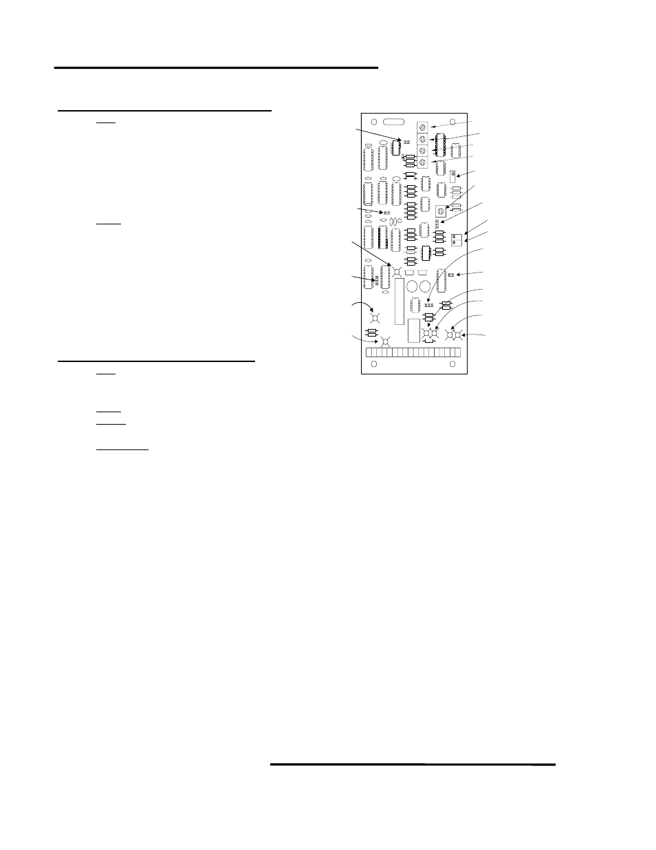
SPEED CONTROLLER BOARD 147-101
JP1 - “10% REGEN” Jumper - When installed,
allows Regen Current Limit up to 150%, when
removed, limits to 10% of full load current.
2QOP - “2Q Operation” Jumper - Leave this jumper installed. Removing it disables the Current loop.
DIR/RL - “ACCEL/DECEL Range” Jumper - Installing this jumper sets the ACCEL and DECEL rates to 2 to 90
seconds (approximately). With this jumper removed, ACCEL/DECEL rates are set for 50 ms to 2 seconds.
RAMP
STOP - “RAMP STOP” Jumper - When this jumper is installed, the drive will decelerate at the DECEL rate to
zero speed and then shut off. If this jumper is removed, the drive shuts off as soon as the stop button is pressed.
2Q/4Q - “DIRECTION MODE” Jumper - The jumper marked 2Q/4Q actually controls the direction jumper’s mode. In
the 4Q position, the jumper sets the direction in Jog mode. This can be used to jog in the direction opposite the running
direction. In the 2Q position, the motor rotation direction is determined by the position of the FWD/REV jumper. In
Analog mode, the reference polarity must agree with the direction jumper or the drive will clamp the input reference to
zero. In Digital mode, the FWD/REV jumper can be used to set the motor direction.
FWD/REV
- “DIRECTION” Jumper - The direction jumper works with the 2Q/4Q jumper. See above.
P4
RUN
1 2 3 4 5 6 7 8 9 10 11 12 13 14 15 16 17 18
TB1
RAMP STOP
FWD/REV
JUMPER
ENABLED
JOG SPD
ACCEL
GAIN
JP1
SPEED CONTROLLER
BOARD
STAB
MCL
RCL
MAX SPD
DECEL
2Q
OP
REGEN
ESTO
P
RUN
JOG
HOLD
RAMP STOP
JUMPER
2Q/4Q
JUMPER
DIR/RL
JUMPER
CURRENT
LIMIT