How do i – PowerTec Regenerative Brushless DC Motor Control 1000AR User Manual
Page 18
Model
1000AR
Installation and Operation Manual
P
AGE
17
OFFICIAL 6/4/2001
HO W DO I …
CONNECT THE REGENERATIVE RESISTORS TO THE MODEL
1000AR?
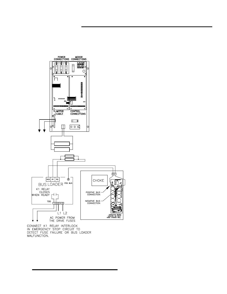
All but the largest Model 1000AR drives have the bus
loader (149-201)built into the chassis. The bus loader mounts
on the lower left-hand side panel and it plugs directly to the
driver board. The power components for the bus loader are on
the lower third of the chassis.
You must include the interlock between terminals TB5-1
and TB5-3 in the control circuits. You must locate the drive’s
regenerative resistors outside the enclosure in a clean, dry,
well-ventilated area.
You MUST connect the regenerative resistors. The
horsepower of the drive, the inertia of the load, and the duty
cycle for regeneration determines the number of resistors
We use a standard 10% duty cycle for stopping duty and
for light regenerative loads. The standard resistor package is
NOT guaranteed to handle all situations. IT IS THE
RESPONSIBILITY OF THE USER TO SPECIFY THE SIZE OF
THE REGENERATIVE RESISTOR PACKAGE. If necessary,
an engineering evaluation should be made.
The interlock is built into the Bus Loader board. The
interlock will open if the bus loader fuse opens up or if the
board fails to function. If the drive tries to regenerate without
the bus loader operating, the drive will trip.
The separately mounted bus loader (149-
101) should be mounted close to the drive. The
resistors must be mounted in their own cage
outside any enclosure. Mount the resistors in a
clean, dry and well ventilated area away from
personnel.
TB5 terminals 3 and 5 must be connected
to the AC drive power. The drawing shows L1
and L2 connected, but any two of the three
phases can be connected.
The resistors must be connected to the R1
and R2 terminals. All standard resistors are
connected in parallel (see page 10 for resistor
values).
Connect the interlock at TB5 terminals 1
and 2 into the control circuit (see page 15).
Connect the fuse input to the POS BUS
connection on the Capacitor Board. Connect
the NEG terminal to the NEG BUS connection
on the Capacitor Board.
Operating the 1000AR drive without the Bus Loader attached, or with the Bus Loader disabled, will
result in the drive tripping. OverVoltage will occur as soon as regenerative operation is attempted. This
could also result in damage to the drive.
R+ R-
CONTROL
CIRCUIT
INTERLOCK
BUS LOADER
RESISTOR(S)