How do i, Connect a digimax – PowerTec Regenerative Brushless DC Motor Control 1000AR User Manual
Page 30
Model
1000AR
Installation and Operation Manual
P
AGE
29
OFFICIAL 6/4/2001
HO W DO I …
CO NNECT A DI G I M AX® ?
The DIGIMAX
®
is a
crystal-based Speed or
Ratio controller. It creates a
train of pulses to command
the movement of a motor
when the drive is operating
in digital speed mode.
A suitable train of
pulses applied at TB1
terminal 11 (with respect to
TB1-9) of the Model 1000
commands the drive to turn
the motor 3° for each pulse.
However, the drive’s routine
adjustments such as MIN
SPEED, MAX SPEED,
ACCEL, DECEL, and JOG
SPEED are not functional.
The DIGIMAX
supplies
these functions.
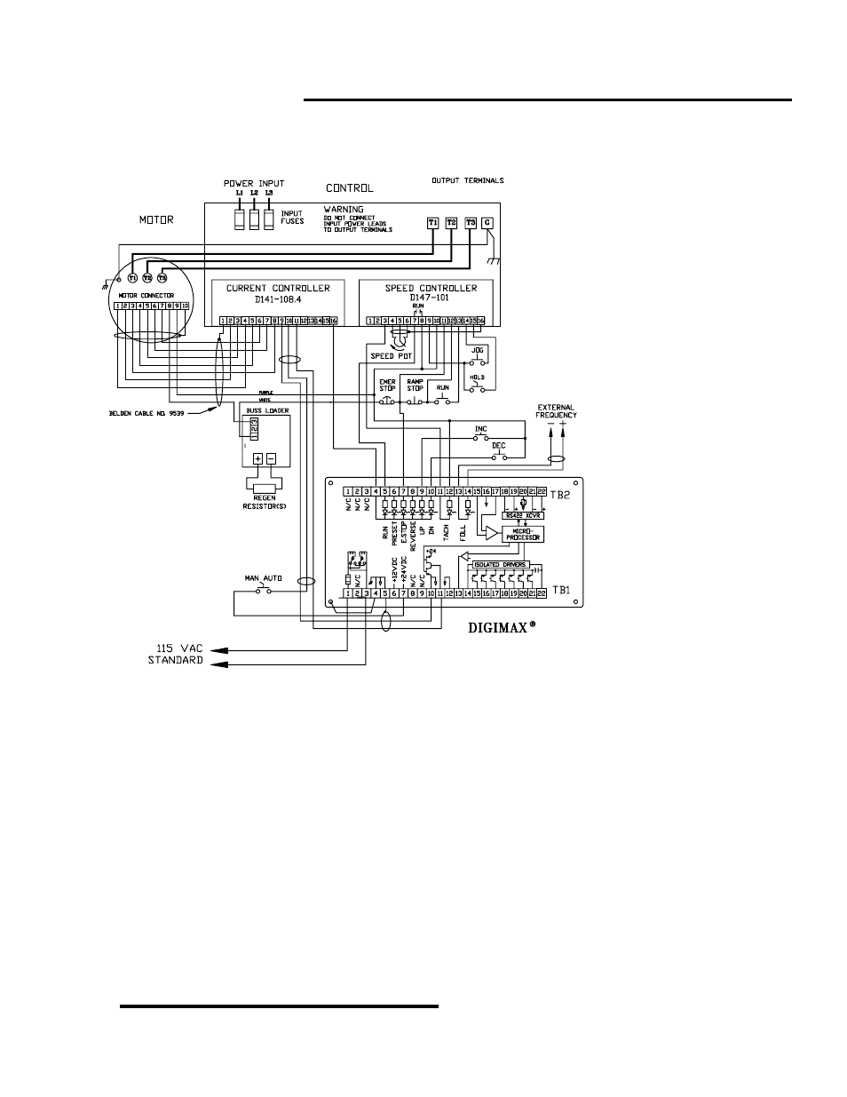
The wiring diagram at
left shows all the basic
connections to the
DIGIMAX. Not all of them
are necessary for all
installations. For instance,
external frequency is only
needed for slave mode.
The power, ground,
and shield connections on DIGIMAX TB1 are necessary. The jumper from TB1-4 goes to a screw in the
back plate.
The pulse train comes from DIGIMAX TB1 terminals 11(+) and 10(-). It is applied to the Model
1000AR TB1 terminals 11(+) and 9(-).
The MAN/AUTO switch may be left out. You can make a straight connection from DIGIMAX TB1-7 to
Model 1000AR TB1-10. Even this connection may be left off if the Current Controller board jumper JP1 is
in the AF position (see page 27).
The DIGIMAX control inputs are on TB2 terminals 5 through 10. These inputs require +24VDC. TB2
terminal 4 is the common connection for these isolated inputs. RUN (terminal 5) and ESTOP (terminal 7)
are required for DIGIMAX operation. PRESET (terminal 6) is an optional second speed. The REVERSE
input (terminal 8) must operate in conjunction with the drive’s reverse, if it is used.
The EXTERNAL FREQUENCY input (TB2 terminals 13 and 14) is only used in the SLAVE mode. It is
used when the DIGIMAX is to follow another pulse train from another DIGIMAX or drive.
The input at DIGIMAX TB2 terminals 15, 16, and 17 in an optional motor load reading signal.
For further information, refer to the DIGIMAX Installation and Operation Manual.