Patton electronic 2085 User Manual
Page 8
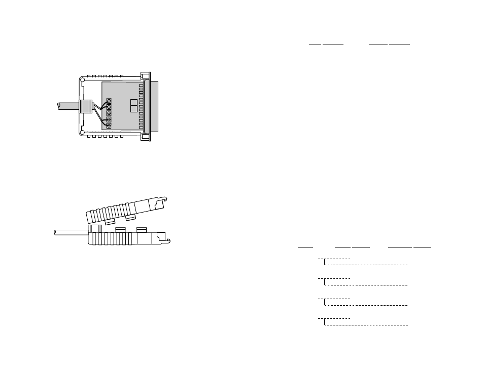
9. Insert the strain relief assembly with the wire going through it
into the slot in the bottom half of the modem case and set it into the
recess in the case.
10. BEND the top half of the case as necessary to place it over the
strain relief assembly. Do not snap the case together yet.
11. Insert one captive screw through a saddle washer and then
insert the captive screw with the washer on it, through the hole in the
DB-25 end of the case. Snap that side of the case closed. Repeat the
process for the other side. This completes the cable installation
process.
4.1.4 2-WIRE CONNECTION
Most RS-485 devices employ a two-wire, half duplex configuration.
When using this configuration, be sure to first set the Model 2085 to
"two wire" mode—then use
only the transmit (XMT) pair
as shown on
the following page.
2085 SIGNAL
RS-485 SIGNAL
XMT+ ....................................+
XMT- .....................................-
The above wiring pattern applies regardless of whether you are
making the RS-485 connection via DB-25, RJ-11, RJ-45 or terminal
blocks. For specific wiring instructions, please refer to the previous
pages of Section 4.
4.2 WIRING FOR MULTIPOINT CIRCUITS
The Model 2085 supports multi-point applications using either a
star or daisy chain topology. Both topologies require special wiring, as
well as specific DIP switch settings for master and slave units. Note:
Refer to Section 3.2.2 for multipoint DIP switch settings.
4.2.1 STAR TOPOLOGY
Using a star topology, you may connect several Model 2085s
together in a master/slave arrangement. Maximum distance between
the units will vary based upon the number of drops, data rate, wire
gauge, etc. Call Technical Support for specific distance estimates.
Figure 7 (below) shows how to wire the two-pair cables properly for
a Model 2085 star topology. Note that the ground connection is not
needed.
13
14
HOST
FIRST SLAVE
SECOND SLAVE
XMT+
RCV+
RCV+
XMT-
RCV-
RCV-
RCV+
XMT+
XMT+
RCV-
XMT-
XMT-
Figure 7. Star wiring for Model 2085 host and slaves