Patton electronic 2085 User Manual
Page 5
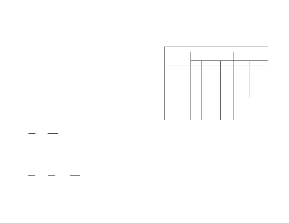
3.4 CONFIGURATION SWITCH APPLICATIONS
The switch settings
generally
needed to configure the Model 2085
for various applications are shown in the table below. Note: Do not
change switch settings until you have
carefully
read Section 3.3.
S1-4: Echo Mode
The setting for switch S1-4 determines whether the Model 2085
echoes data back to the transmitting device (half-duplex mode only).
S1-4
Setting
On
Echo On
Off
Echo Off
S1-5: Carrier Control Method
The setting for switch S1-5 determines whether the carrier is
“Constantly On” or “Controlled by RTS”. This setting allows for
operation in switched carrier, multipoint and/or hardware handshaking
applications.
S1-5
Setting
On
Controlled by RTS
Off
Constantly On
S1-6: Receive Impedance
The setting for switch S1-6 selects the impedance of the input
receiver. You may select either a “low” impedance of 120 Ohms or a
“high” impedance of 16 kOhms. By selecting the proper impedance for
each drop, there may be up to 50 receivers in one application.
S1-6
Setting
On
Low (120 Ohm)
Off
High (16 kOhm typical)
S1-7 and S1-8: 2-Wire/4-Wire Modes
Switches S1-7 and S1-8 are set together to determine whether the
Model 2085 is in 2-wire or 4-wire operating mode. Note: 2-wire mode
is half-duplex only.
S1-7
S1-8
Setting
On
On
2-wire mode
Off
Off
4-wire mode
7
8
S1-1: “Xmt Off” Imp.
OFF
OFF
OFF
OFF
OFF
S1-2: “Xmt Off” Imp.
OFF
OFF
OFF
OFF
OFF
S1-3: RTS/CTS Delay
ON
ON
ON
OFF
ON
S1-4: Echo
OFF
OFF
OFF
OFF
OFF
S1-5: Carrier Control
OFF
ON
ON
Master-OFF
ON
Slaves-ON
S1-6: Rcv Impedance
ON
ON
ON
Master - ON
Slaves - OFF
Last Slave - ON
S1-7: 2-wire/4-wire
OFF
OFF
ON
OFF
ON
S1-8: 2-wire/4-wire
OFF
OFF
ON
OFF
ON
TYPICAL MODEL 2085 APPLICATIONS
Point-to-Point
Switch
Settings
Multi-point
4W
2W
4W
2W
4W HDX