Polycom VSX 3000 User Manual
Page 13
Non-Proprietary Security Policy, Version 1.0
June 15, 2007
Polycom VSX 3000, VSX 5000, and VSX 7000s
Page 13 of 23
© 2007 Polycom, Inc. -
This document may be freely reproduced and distributed whole and intact including this Copyright Notice.
•
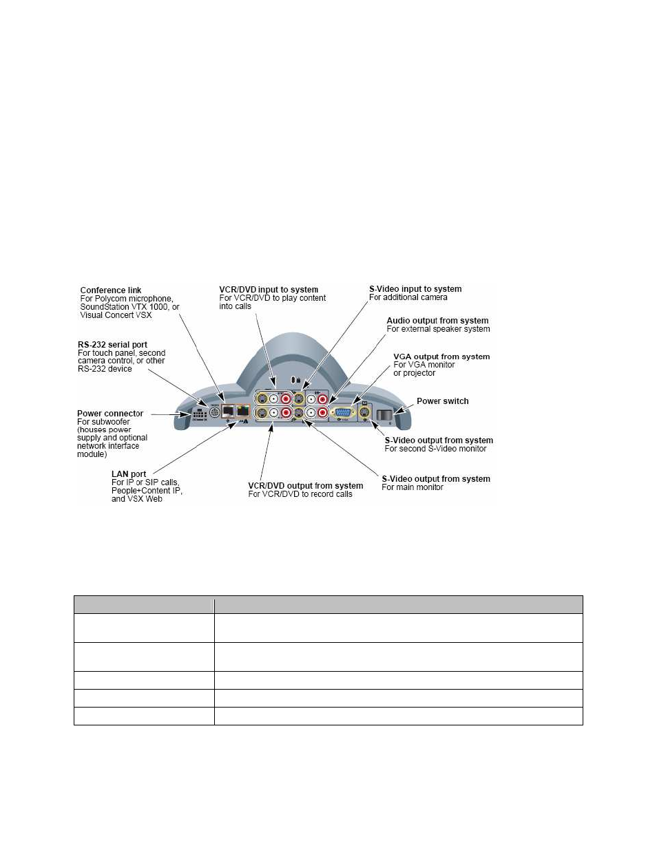
LAN connector – For IP calls, VSX Web, and remote management
•
Conference link connector – For microphone pod, SoundStation VTX 1000, or Visual concert VSX
•
VGA connector – Output from system for VGA monitor or projector
•
VCR/DVD connector – Play VCR/DVD connect into calls or record call content
•
Power switch
•
S-Video connector – Input from camera or output to S-Video monitor
•
Audio connector – Output from system for external speaker system
•
Serial RS-232 port – RS-232 port for touch panel, camera control, or other RS-232 device
•
IR Sensor – Input from IR sensor
•
Speaker – Built-in speaker
•
Camera – Input for video conferencing
•
LED – LEDs indicate system status
Figure 9 - VSX 7000s Back Panel
Section 1 of the Administrator’s Guide for the VSX Series lists the connection cables required for the system. The
following table maps VSX 7000s interfaces with FIPS 140-2 logical interfaces.
Table 5 - Mapping of FIPS 140-2 Logical Interfaces to VSX 7000s Interfaces
FIPS 140-2 Logical Interface
VSX 3000, VSX 5000, and VSX 7000ss Port/Interface
Data Input
LAN connector, Conference link connector, VCR/DVD connector, Serial port, S-Video
connector, Camera
Data Output
LAN connector, VGA connector, VCR/DVD connector, S-Video connector, Audio
connector, Serial port, Conference link connector, Speaker
Control Input
LAN connector, Serial port, Conference link connector, IR Sensor, Power switch
Status Output
LAN connector, VGA connector, Serial port, Conference link connector, LEDs
Power
Power connector
The following is the list of ports and interfaces of the VSX 8000 system and Figure 10 below shows the ports on
module’s connector panel.