Polycom VSX 3000 User Manual
Page 10
Non-Proprietary Security Policy, Version 1.0
June 15, 2007
Polycom VSX 3000, VSX 5000, and VSX 7000s
Page 10 of 23
© 2007 Polycom, Inc. -
This document may be freely reproduced and distributed whole and intact including this Copyright Notice.
•
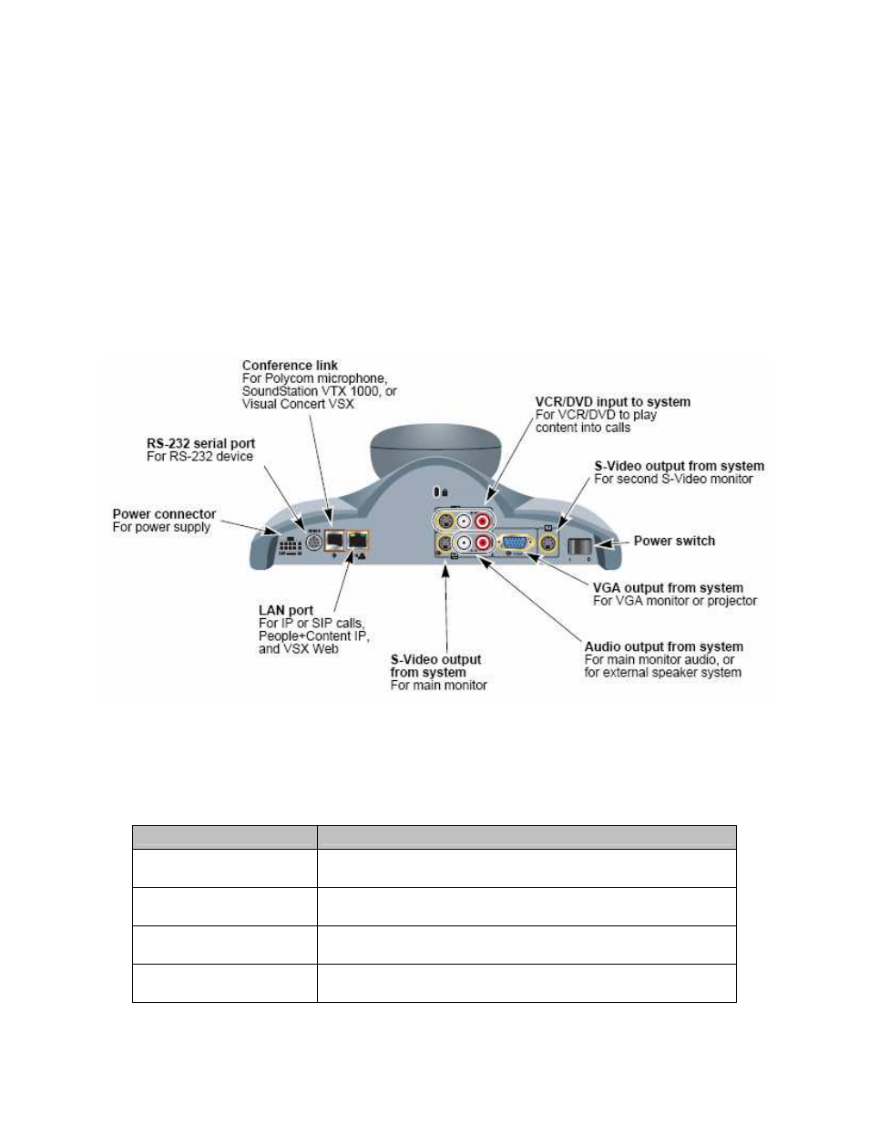
LAN connector – For IP calls, VSX Web, and remote management
•
Conference link connector – For microphone pod, SoundStation VTX 1000, or Visual Concert VSX
•
VGA connector – VGA connector for input and passes the video image for monitor or projector
•
VCR/DVD inputs – For VCR/DVD to play content into calls
•
Power switch – To power up or down the device
•
Audio connectors – For main monitor audio, or for external speaker system
•
S-Video Connector – S-Video output for monitor
•
Serial port – RS-232 port for RS-232 device
•
IR Sensor – Input from IR sensor
•
Speaker – Built-in speaker
•
Camera – Input for video conferencing
•
LED – LEDs indicate system status
Figure 7 - VSX 5000 Back Panel
Section 1 of the Administrator’s Guide for the VSX Series lists the connection cables required for the system. The
Following table maps VSX 5000 interfaces with FIPS 140-2 logical interfaces.
Table 3 - Mapping of FIPS 140-2 Logical Interfaces to VSX 5000 Interfaces
FIPS 140-2 Logical Interface
VSX 3000, VSX 5000, and VSX 7000s Port/Interface
Data Input
LAN connector, VGA connector, VCR/DVD inputs, Conference link
connector, Serial Port, Camera
Data Output
LAN connector, VGA connector, Audio connectors, S-Video Connector, Serial
Port, Conference link connector, Speaker
Control Input
Conference link connector, LAN connector, Serial Port, IR Sensor, Power
switch
Status Output
VGA connector, S-Video connector, LAN connector, Serial Port, Conference
link connector, LEDs