Connections – Philips DSR 1000 User Manual
Page 5
4
CONNECTIONS
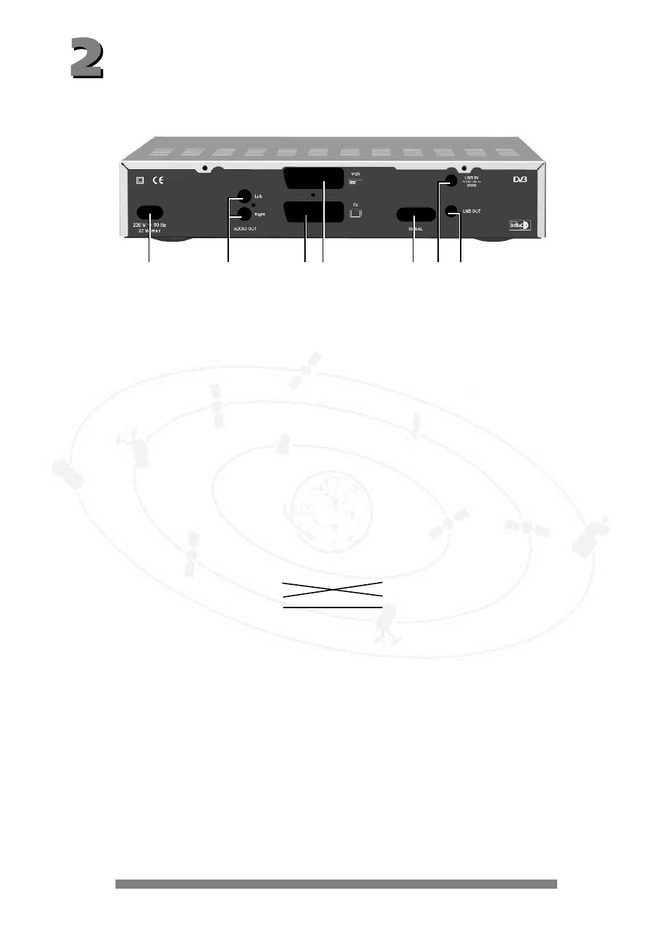
The following connections are located on the back of the unit:
1 - 230 V/50 Hz:
Connect the power cable to the power socket.
2 - AUDIO TV L & R:
Audio output, left and right-hand channel for connecting to a stereo unit.
3 - TV:
Connect the TV connection socket to your television unit using the
SCART cable supplied.
4 - VCR:
VCR SCART socket for connecting a video recorder.
5 - DATA INTERFACE: RS 232 interface for serial data transfer during servicing.
0-modem cable (pins 2 and 3 crossed, pins 1, 4, 6-9 are not used).
Receiver:
PC:
Pin 2 = RXD
Pin 2 = RXD
Pin 3 = TXD
Pin 3 = TXD
Pin 5 = GND
Pin 5 = GND
6 - SAT-IF INPUT:
Sat-IF signal input and output for LNB supply and control signals
connect the cable of your satellite unit to this socket.
7 - SAT-IF OUTPUT:
IF signal output (e.g. for feeding through an analogue receiver).
Note:
The label showing the type and serial number is underneath your receiver.
1
2
3
4
5
6
7
- DSX 5540 (36 pages)
- SLV5405 (13 pages)
- 37PFL66X6H (68 pages)
- STU 801/25R (28 pages)
- DSR 310/00 (2 pages)
- Magnavox PR 1309B (8 pages)
- US2-MANT510 (2 pages)
- US2-MANT510 (14 pages)
- DSX5500 (2 pages)
- STU909/55M (27 pages)
- STU811/02G (31 pages)
- SWW1810 (22 pages)
- PT9000/12 (2 pages)
- SVC2543W (2 pages)
- TDA8303 (21 pages)
- Digital Cable Receiver DCR2022 (2 pages)
- SDV1121T/27 (10 pages)
- SDV2927 (24 pages)
- DSX 5350 (48 pages)
- PVD778 (4 pages)
- PVD778 (20 pages)
- 22IE (85 pages)
- 22IE (81 pages)
- 14PT1353 (2 pages)
- DSX 5353 (43 pages)
- US2-MANT410 (7 pages)
- MATCH LINE 32PW9544 (18 pages)
- STU 901/25R (30 pages)
- Digital Audio Satellite Receiver DR500 (47 pages)
- SBCHC8372 (2 pages)
- DSR2010 (49 pages)
- DSR320 (2 pages)
- PVD1079/12 (39 pages)
- PT902/37 (2 pages)
- 15PT1767 (2 pages)
- PR 0920X (8 pages)
- Indoor Antenna (16 pages)
- MATCH LINE 28PW9513/32 (2 pages)
- HC 8372 (85 pages)
- PVD900/37 (30 pages)
- SDV2750/27 (20 pages)
- US2-MANT940 (2 pages)
- US2-MANT940 (16 pages)
- AZ3068 (1 page)