Figure 10, Figure 11, Speaker outputs l r – Polk Audio Subwoofer PSW1200 User Manual
Page 19
15
your amplifier to the red (+) terminal on
your speaker, and the wire from the
black (-) terminal of the amplifier to the
black (-) terminal on your speaker. Most
wire has some indication (such as color-
coding, ribbing, or writing) on one of the
two conductors to help maintain consis-
tency. If your Subwoofer does not seem
to produce much bass, it is most likely
that one of the speaker wires is con-
nected backwards. Double-check all
connections for correct polarity.
Strip 1/2” of insulation from each of the
two conductors on both ends to expose
the bare wire. Twist the exposed wire of
each conductor to form two un-frayed
strands. Connect two conductors to the
receiver or amp (refer to the owner’s
manual supplied with your electronics
for assistance with proper hookup).
Connect the two conductors on the other
end of the wire to the speaker termi-
nals. Repeat for the other channel.
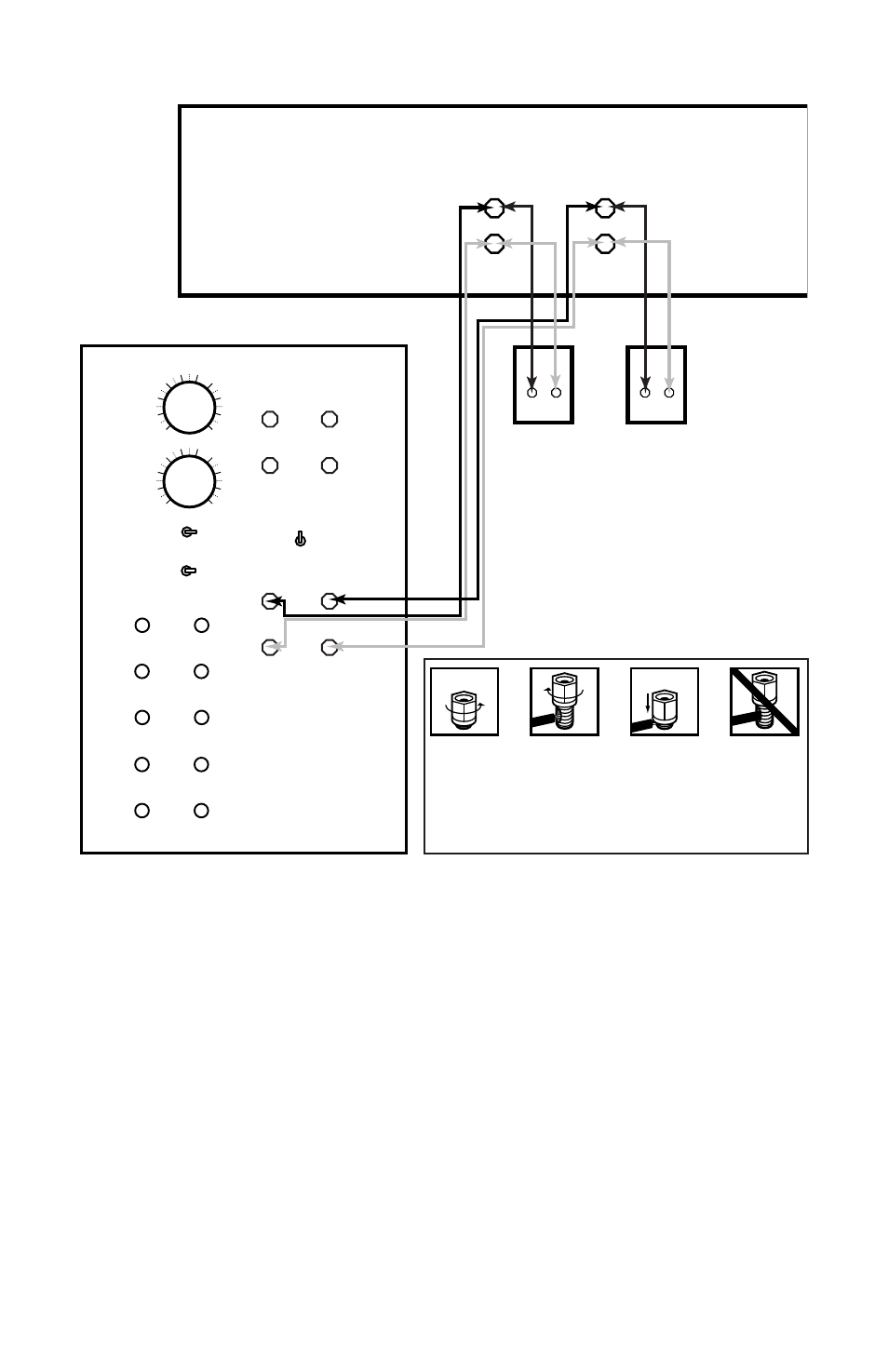
To connect wire to the binding post,
unscrew the plastic hex nut on the bind-
ing post and insert the bare wire into
the hole near the base of the binding
post (Fig. 11). Do not insert the insu-
lated part of the wire into the hole, as
this will not give you a good connection.
Twist the hex nut back down the binding
post until it firmly meets the wire. Do
not over-tighten.
SURROUND RECEIVER OR PREAMP/PROCESSOR
VARIABLE
LOW PASS
CROSSOVER
40Hz
120Hz
VARIABLE
PHASE
ALIGNMENT
0
°
180
°
SWITCHABLE
HIGH PASS
CROSSOVER
(SPEAKER LEVEL)
SWITCHABLE
HIGH PASS
CROSSOVER
(LINE LEVEL)
40HZ 80HZ
40HZ
80HZ
FULL RANGE
POWER
FRONT
FRONT
LEFT
OUT
LEFT
IN
LEFT
REAR
IN
CENTER 1
IN
FRONT
RIGHT
OUT
RIGHT
FRONT
IN
RIGHT
REAR
IN
CENTER 2
IN
LFE/SUBWOOFER IN
FRONT SPEAKER LEVEL OUT
L R
L R
FRONT SPEAKER LEVEL IN
SPEAKER OUTPUTS
L
R
+
–
+
–
+ –
+ –
ON
OFF
AUTO
+
–
+
–
FIGURE 10.
Insert
speaker
wire
through
hole
Tighten
hex nut
Do not
insert
insulated
section
through
hole
Loosen
hex nut
FIGURE 11.