Patton electronic 2190 User Manual
Page 4
3.0 INSTALLATION
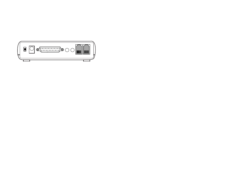
The Model 2190 is equipped with one RS-232 Serial Port, two
RJ-11 connectors, 2 jack hook-ups (1 microphone, 1 speakerphone), 1
AC power source and a power switch. Figure1 below, shows the rear
panel of the Model 2190 and the location of these connectors.
Following figure 1 are sections describing proper installation of each
connector.
Figure 1. Model 2190 Rear Panel Connectors
3.1 CONNECTING TO THE SERIAL PORT
The serial port on the Model 2190 is a RS-232 port. Use the sup-
plied cable to connect to the modem, the computer, or terminal.
3.2 CONNECTING TO THE PHONE LINES
On the Model 2190 there are two phone lines (jacks). The “Line”
jack is for the user to connect to the public telephone line.
The “phone” jack is for the user to connect to the telephone set.
You can use the telephone set, when the modem is not connected to
another modem.
3.3 CONNECTING TO THE MICROPHONE (MIC)
The external microphone (MIC) jack is valid only when the voice
option is selected.
3.4 CONNECTING TO THE SPEAKER (SPKR)
The External speaker (SPKR) jack.
3.5 CONNECTING POWER
The power source input. Put the other end into the wall outlet of
the AC power source.
3.6 POWER
Power Switch.
3.7 MODEM DRIVER
If it is required to install the Modem, use the supplied modem driv-
er disk.
4.0 CONFIGURATION
Before attempting to configure or operate the Model 2190, it is
important to know how the unit will handle command entry. This section
provides command guidelines, AT command set, dial codes, sub para-
meter definitions, fax commands, and voice commands.
4.1 COMMAND GUIDELINES
• All commands must be preceded by "AT" (ATtention code) except
for the “A/” command and "+++" escape command.
• AT commands are not case sensitive and can be entered in lower
case or uppercase characters.
• AT commands cannot be deleted by the backspace key or by the
delete key.
• The Attention Code is used by the modem to determine the speed
and data format of the in coming data from the DTE.
• More than one command can be entered in one command line
and may be separated by space for readability.
• The command line can NOT exceed 40 characters excluding the
attention code and must be ended by the ASCII character speci-
fied by S register 3.
• The default of the S register 3 is the decimal 13 -- "Carriage
Return"
• A line without carriage return will be ignored.
• Commands following the AT are processed after receiving the
"Carriage Return" character, and the space added for readability
will be ignored.
• Any parameters following the AT command that were ignored will
be treated as equal to 0.
Power Power
Serial Port
MIC. SPK.
Phone
Line
5
6