Chapter 3, Operation – Lakeshore Learning Materials 647 User Manual
Page 27
Lake Shore Model 647 Magnet Power Supply User’s Manual
Operation
3-1
CHAPTER 3
OPERATION
3.0 GENERAL
This chapter covers seven areas: MPS Front Panel (Paragraph 3.1), Power Up (Paragraph 3.2), Setting
Current on an MPS with Manual PSH Control (Paragraph 3.3), Setting Current with Automatic PSH Control
(Paragraph 3.4), Instrument Setup Screens (Paragraph 3.5), Function Menus (Paragraph 3.6), and an
Automatic Persistence Control Example (Paragraph 3.7).
Setup the MPS software with the MPS output terminals shorted together as in section 3.2. This ensures that
while the user learns MPS operation, an inadvertent keystroke causes no damage to the magnet.
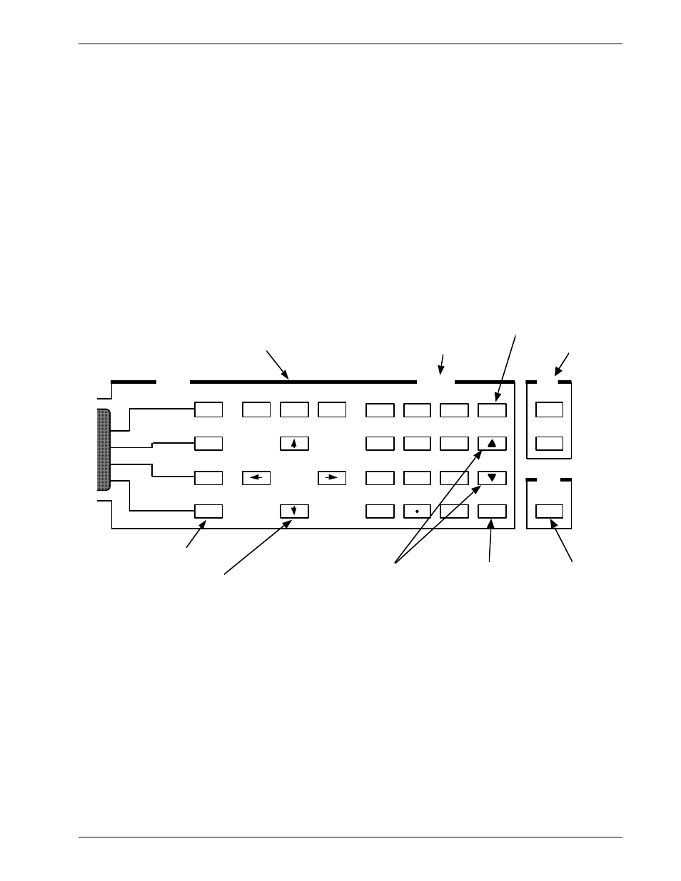
3.1 THE MPS FRONT PANEL
Figure 3.1 below shows the MPS Front Panel. The up or down Display Cursor Control keys move the line
indicator to the line containing a value to be changed. Use either the Data Entry Keypad to enter the desired
value or the up or down Numeric Entry keys to increment or decrement the value. The Enter key accepts the
update, while the Esc key discards the change and returns to the prior value. Move the cursor to a particular
digit with the right and left Display Cursor Control keys and change it with the Numeric Entry keys.
Function
Menu
Next
Menu
Normal
Display
Cursor
Mode
Local
Remote
Output
Inhibit
7
8
9
Esc
4
5
6
1
2
3
0
+/–
Enter
Data Entry
Functions
Display Menu Select Keys
Display Function Keys
Display Cursor Control Key
Data Entry Keypad
Interface Keys
Enter Key
accepts a change
Esc Key returns to prior value
Numeric Entry
Increment and Decrement Keys
Output
Inhibit Key
Figure 3-1
Front Panel Numeric Entry Keys
3.2 POWER
UP
Read and follow instructions in Paragraphs 2.1 - 2.4.3 and the Forward safety recommendations before
applying power to the MPS. Do not connect the MPS to the magnet yet. Short the output terminals together
with a #4 gauge or larger cable to protect the magnet against incorrect configurations.
Turn on the MPS. It requires approximately 2 seconds for initialization. Initially, all front panel annunciators
come on and the alarm sounds for a short time. Within 1 second, the Fault and Persistent Switch Heater On
annunciators and the alarm turn off. If the MPS detects a high or low AC line fault, it blinks the front panel
Fault annunciator and turns off the input circuit breaker. If this occurs, verify that the AC source matches the
line voltage listed on the MPS rear panel.
Initially, the entire display clears and the alarm sounds for a short time. The MPS initializes itself and displays
the model identification. The Normal Display screen appears with a blinking asterisk indicating each update
when the unit is in normal operation.
CAUTION: Set magnet parameters according to manufacturer's specifications. Failure to do so may
damage the magnet and threaten user safety.