0 voltage programming procedure, Figure 17 load level indicators, Oltage – Liebert PSITM User Manual
Page 25: Rogramming, Rocedure
Voltage Programming Procedure
21
9.0
V
OLTAGE
P
ROGRAMMING
P
ROCEDURE
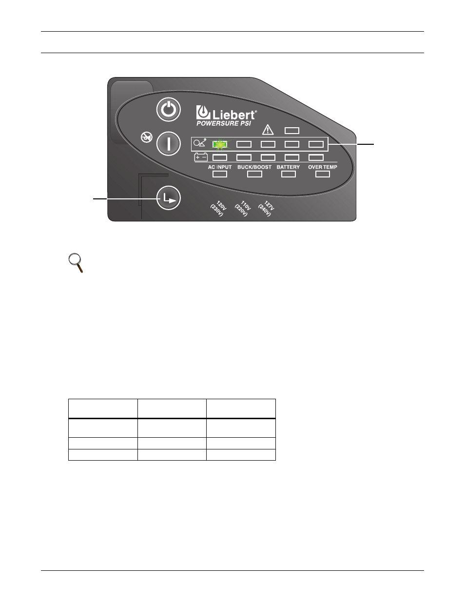
Figure 17 Load Level Indicators
1. Remove the front bezel from the UPS.
2. UPS must be operating in Normal (AC) mode.
3. The AC Input, Load, and Battery Level Indicators should be lit.
4. Press the Voltage Programming button for at least 5 seconds to enter the Configuration mode.
The UPS will beep and all of the indicators on the front panel display will flash on and off for
approximately 5 seconds. The next cycle will display the current configuration, either 220, 230 or
240 VAC. One of the Load Level Indicators will be flashing. Initially, the 0%-25% Load Level
Indicator will be flashing, indicating the default setting of 230V as shown in Figure 17.
5. Press the ON button to step through the voltage settings until the appropriate Load Level
Indicator is flashing.
6. Press the Voltage Programming button. The UPS will return to Normal mode operation.
The Voltage Programming button allows the operator to select the mains transfer voltage at which
the UPS will switch to battery power. This also changes the inverter voltages. The voltage settings
are as follows:
NOTE
Mains power will be applied to the connected load.
Setting
Input Voltage
Range
Output Voltage
(Battery Mode)
120V (230V)
166 - 272VAC
(default)
230VAC
110V (220V)
158 - 260VAC
220VAC
127V (240V)
172 - 283VAC
240VAC
Load Level
Indicators
Voltage
Programming
Button