Lennox Hearth Winslow (PS40) User Manual
Page 12
1
NOTE: DIAGRAMS & ILLUSTRATIONS ARE NOT TO SCALE.
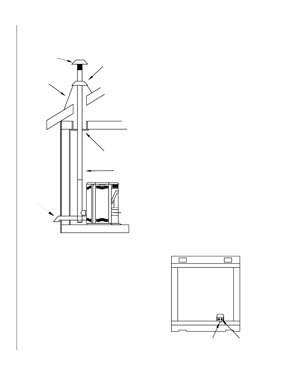
Mobile Home Installations
The following are required for installation of the Winslow™ PS40 stove in
mobile homes. See Figure 20.
1. Connecting the Winslow PS40 stove to outside combustion air is
optional, except in mobile home installations and when required by
local building codes. The stove’s air intake will accept 3” ID pipe to
accommodate outside air installations. The air intake on the exterior
of the home should always be located substantially below the flue ter-
mination and terminate with a cover to keep out weather and pests.
2. The stove must be fastened to the floor using lag screws. The screws
can be inserted through the holes in the pedestal located behind the
side doors.
3. The stove must be grounded with a #8 or larger copper wire.
WARNING: DO NOT INSTALL THIS STOVE IN A SLEEPING ROOM
IN A MANUFACTURED HOME.
CAUTION: THE STRUCTURAL INTEGRITY OF THE MANUFAC-
TURED HOME FLOOR, WALL AND CEILING/ROOF MUST BE
MAINTAINED.
Vertical
If the length of pipe exceeds 15 feet, 4 inch pipe rather than 3 inch vent
pipe should be used.
Outside Air Installations
Connecting the Winslow PS40 stove to outside combustion air is optional,
except in mobile home installations and when required by local build-
ing codes. The stove’s air intake will accept 3” ID pipe to accommodate
outside air installations. The air intake on the exterior of the home should
always be located substantially below the flue termination and terminate
with a cover to keep out weather and pests.
Thermostat installation
The Winslow PS40 stove can be operated manually or by thermostat. The
stove comes from the factory wired to operate manually - see control
board operation on the following page. A low voltage thermostat can be
installed on the stove. To install the thermostat:
1) Unplug the stove from the electrical outlet. Open the right side door
and lift out the control board from its retaining brackets. Locate the
light green wiring block at the bottom back of the board (see Figure
21), loosen the two screws B at the back of the block and remove the
U shaped jumper wire A protruding from the block.
2) Insert a wire from the thermostat into one of the slots from which
the jumper wire was removed. Repeat this process for the other
thermostat wire.
Retain the jumper wire for future reinstallation. See Page 19 for thermostat
operation instructions.
IMPORTANT NOTE: Install the thermostat per the manufacturers
instructions, provided with the thermostat. Failure to follow
manufacturers instructions could result in a malfunction. Pay
special attention to the thermostat location requirements. If the
location requirements are not adhered to the appliance, erratic
operation or failure may occur.
Do not mount the thermostat where it may be affected by:
• Radiant heat from the stove, fireplaces, sun or other heat
sources.
• Drafts or dead spots behind doors or in corners.
• Hot or cold air from ducts.
Listed Pellet Pipe
Ceiling Firestop
Storm Collar
Roof Flashing
Rain Cap
Outside Air Pipe
Figure 20
Figure 21
Wiring Block
B
A
Rear View of Control Board
A = Jumper Wire
B = Screws
A
B
Rear View of Control Board
Wiring Block