Troubleshooting – Lochinvar 400-801 User Manual
Page 39
3
Troubleshooting
(continued)
39
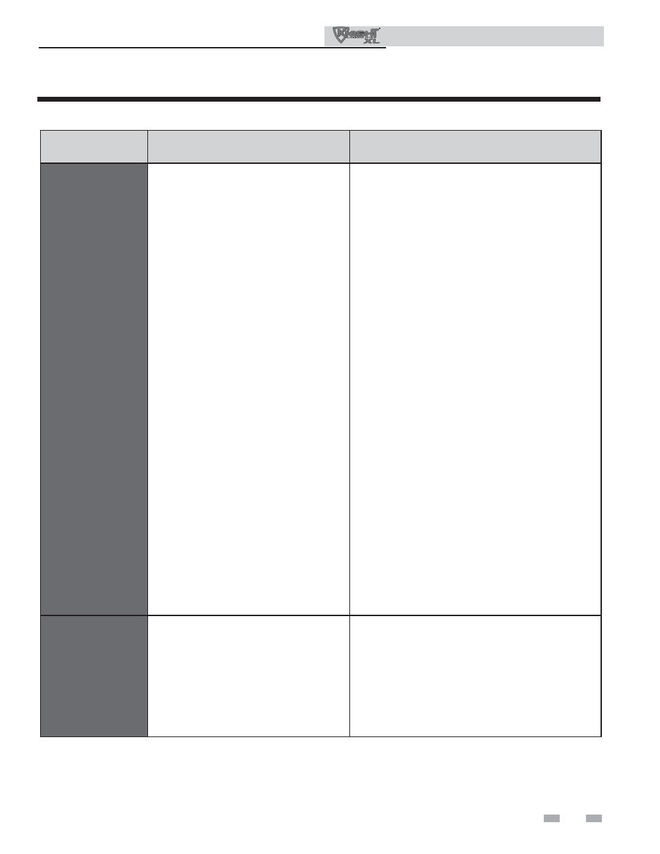
Table 3-4 (continued from previous page) Troubleshooting Chart - Fault Messages Displayed on Boiler Interface
Service Manual
FAULT
DESCRIPTION
CORRECTIVE ACTION
Flame Fail Ign
(cont’d)
(will require a manual
reset once the condition
has been corrected.
Press the RESET button
on the SMART SYSTEM
display to reset.)
The unit has failed to prove main burner
ignition after four (4) attempts.
• Verify that the plastic hose from the gas valve to the air
inlet is connected and is not damaged.
• Verify that the vent/air intake pipes are correctly
installed and that there are no obstructions.
• Check for 24 vac to the gas valve at the 2-pin
connection on the side of the main control board during
the ignition attempt. If no voltage is present, replace
the main control board.
• If 24 vac is present at the main control board, check
the wiring between the main control board and the gas
valve. Replace the wiring if necessary. Do not
disconnect the wiring from the gas valve and attempt to
measure voltage at that point. The main control board
can detect if the gas valve is not connected and will
display the Gas Valve or Gas Valve Fail fault.
• If 24 vac is present, check the outlet of the valve to
ensure the valve is flowing gas. With a manometer
connected to the outlet tap of the gas valve, when the
unit is in the prepurge period, there should be a
negative pressure present. When the valve is
energized a change in pressure should occur. If the
pressure change does not occur, the gas valve is not
opening. Replace the gas valve.
•
Inspect flame sensor and associated wiring.
Reference page 31 of this manual for removal and
cleaning procedures. Replace if necessary.
• Inspect and clean the heat exchanger as necessary.
Reference page 32 of this manual for cleaning
procedures.
• Inspect the burner. Reference page 31 of this manual
for removal and cleaning procedures. Replace if
necessary.
• Replace the main control board.
Flame Sequence
(will require a manual
reset once the condition
has been corrected.
Press the RESET button
on the SMART SYSTEM
display to reset.)
The flame detector circuit is seeing a flame
signal while no flame is present.
• Check supply voltage for proper polarity.
• Check external wiring for voltage feedback.
• Check the flame rod and make sure it is clean.
• Check the internal wiring for bad connections.
• Replace main control board.