Lennox Hearth INTERTEK LMBV-42REN User Manual
Page 6
6
NOTE: DIAGRAMS & ILLUSTRATIONS ARE NOT TO SCALE.
LENNOX HEARTH PRODUCTS • MERIT
®
SERIES B-VENT GAS FIREPLACES • 42" LMBV MODELS • INSTALLATION INSTRUCTIONS
CLeARANCeS
Minimum clearance to combustibles for the
appliance is as follows: sides and back - 0" (0
mm), floor - 0" (0 mm), adjacent wall - 0" (0
mm), ceiling - 64" (1625 mm). Service Clear-
ances, Front - 3' (0.9 m).
NOTE: 3" (75 mm) minimum clearance is
required above any inclined vent component.
1" minimum clearance is required to the sides
of vertical vent.
Hearth extension
- A hearth extension is not
required with this appliance. If a hearth exten-
sion is used, do not block the lower control
compartment door. Any hearth extension used
is for appearance only and does not have to
conform to standard hearth extension instal-
lation requirements.
Wall Finishes / Surrounds / mantels
NOTE: Combustible wall finish materials and/
or surround materials must not be allowed to
encroach the area defined by the appliance
front face (black sheet metal). Never allow
combustible materials to be positioned in
front of or overlapping the appliance face.
Non-combustible materials, such as surrounds
and other appliance trim, may be installed on
the appliance face with these exceptions: they
must not cover any portion of the removable
glass panel or control compartment.
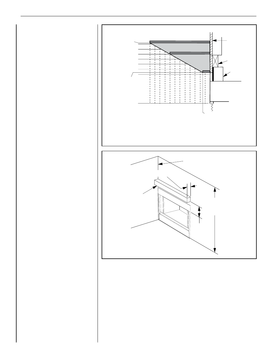
Vertical installation clearances to combustible
mantels vary according to the depth of the
mantel. See Figure 6. Mantels constructed of
non-combustible materials may be installed
at any height above the appliance opening;
however, do not allow anything to hang below
the fireplace hood.
Minimum clearance requirements include any
projections such as shelves, window sills,
mantels, etc. above the appliance.
NOTE: We recommend the use of high tem-
perature paint (rated 175° F or higher) on the
underside of the mantel.
Wall Details and Combustible mantels -
Complete finished interior wall. To install the
appliance facing flush with the finished wall,
position framework to accommodate the
thickness of the finished wall (Figure 6). This
Figure also indicates vertical installation clear-
ances to combustible mantels. Figure 7 also
shows an example of a combustible mantel
shelf projecting a maximum of 12" (305 mm)
from the wall, and which must be installed a
minimum distance of 14-1/2" (368 mm) from
the top of the firebox opening.
Figure 6
Figure 7
Fireplace
Opening
Spacer
Finished
Wall
Header
1
2
3
4
5
6
7
8
9
10
11
12
9
10
11
12
Combustible Mantel Clearances
Inches
Min. Height of Mantel
Above Fireplace
Opening
Max.Length of Mantels
Three mantels are shown (dark gray elongated rectangles)-
one, 1-1/2 in. long at a min. of 8-3/8 in. above the fireplace opening;
the second, 8 in. long at a min. of 12 in. above the fireplace opening;
the third, 12 in. long at a min. of 14-1/4 in. above the fireplace opening;
for any mantels between these three in length, they must be located
within the lighter gray shaded area.
0
0
8-3/8
1-1/2
8
13
14
14-1/4
64"
(1626 mm)
Min. to
Ceiling
14-1/2" Min.
(368 mm)
0" (0 mm) Clearance
to Combustible
Side Wall
Max. Projection 12" (305 mm)
Combustible
Mantel