Warning, Caution, Not for use with solid fuel – Lennox Hearth INTERTEK LMBV-42REN User Manual
Page 10: Step 5. field wiring; install optional wall switch, Millivolt wiring diagram, Figure 14
10
NOTE: DIAGRAMS & ILLUSTRATIONS ARE NOT TO SCALE.
LENNOX HEARTH PRODUCTS • MERIT
®
SERIES B-VENT GAS FIREPLACES • 42" LMBV MODELS • INSTALLATION INSTRUCTIONS
Figure 12
Figure 13
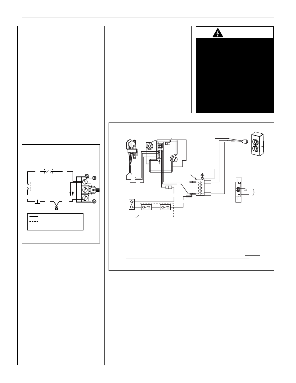
b. electronic Wiring
The electronic appliance must be connected to
the main power supply. To install:
1. Route a 3-wire 120V 60Hz power supply
to the appliance junction box and ground.
(See Figures 13 and 14 ).
2. Locate and install a low voltage (24V)
wall switch (not supplied) in the desired
location. Connect the low voltage wire to
this switch (see Figure 13).
3. After wiring is complete, replace the ap-
pliance junction box cover and secure with
the hex head screws previously removed.
Step 5. Field Wiring; Install Optional
Wall Switch
Refer to Section A, below, for millivolt appliances
and Section B, below, for electronic appliances.
A. millivolt Wiring
The gas valve has been set in place and has
been pre-wired at the factory. No additional
wiring is required unless the optional wall
switch or optional remote control kit is to be
installed. Locate the optional wall switch or
optional remote control in the desired location
and connect the millivolt wire (see Figure 12).
CAUTION: DO NOT CONNeCT THe WALL
SWITCH TO A 120v pOWeR SUppLY.
NOTE: Optional wall switch not supplied. If the
optional wall switch is not installed, the ends of
the 15' coiled wire must be connected with a wire
nut (not supplied) for the appliance to operate.
MILLIVOLT WIRING DIAGRAM
NOTE: If any supplied wire must be replaced,
always use Type AWM, 105°C, 18 GA wire.
BK
BK
BK
TP
TH
BK
WHT
LIMIT
SWITCH
THERMOPILE
*
FACTORY WIRED
FIELD WIRED
*
For optional wall switch attachment only.
DAMPER
SWITCH
TP
TH
* Control Switches: Wall On/Off Switch or Timer, Unit Mounted On/Off Switch, or Remote Control Switch. If an optional
control switch is installed, turn the appliance-mounted ON/OFF burner control switch to the OFF position.
NOTES:
1. If any of the original wire as supplied must be replaced, use Type AWM 105°C - 18 gage wire ONLY.
2. 120 VAC, 60 Hz - Less than 3 Amps.
CAUTION: label all wires prior to disconnection when servicing controls. Wiring errors can cause improper and
dangerous operation. Verify proper operation after servicing.
CAUTION
Ground supply lead must be con-
nected to the wire attached to the
green ground screw located on the
outlet box. See
Figure 14
. Failure to
do so will result in a potential safety
hazard. The appliance must be
electrically grounded in accordance
with local codes or, in the absence of
local codes, the National electrical
Code, ANSI/NFpA 70-latest edition.
(In Canada, the current CSA C22.1
Canadian Electrical Code).
0.375"
0.375"
0.25" Ø
NOT FOR USE WITH SOLID FUEL
CAUTION:
Hot while in operation. Do not
touch. Severe Burns may result. Keep children, clothing,
furniture, gasoline and other liquids having flammable
vapors away.
CAUTION:
Do not operate the appliance with
factory installed refractory panel(s) removed, cracked or
broken. Replacement of the factory installed refractory
panel(s) should be completed by a licensed or qualified
service person.
WARNING:
Improper installation, adjustment,
alteration, service or maintenance can cause injury
or property damage. Refer to the owner’s information
manual provided with this appliance. For assistance
or additional information consult a qualified installer,
service agency or the gas supplier.
Due to high temperatures, keep children, and furniture
away.
Keep burner and control compartment clean. See
installation and operating instructions accompanying
appliance.
WARNING:
Do not connect 120 V AC to the control valve.
THIS APPLIANCE MUST BE INSTALLED IN ACCORDANCE
WITH LOCAL CODES, IF ANY; IF NONE, FOLLOW THE
NATIONAL FUEL GAS CODE, ANSI Z223.1, OR NATURAL
GAS AND PROPANE INSTALLATION CODE, CSA B149.1.
If not installed, and maintained in accordance with the
manufacturer's instructions, this product could expose
you to substances in fuel or fuel combustion which are
known to the state of California to cause cancer, birth
defects, or other reproductive harm.
* For a copy of the homeowner’s care and operation
manual, go to www.lennox.com or call 1-800-9-lennox.
B-VENTED APPLIANCES NEED FRESH AIR FOR SAFE
OPERATION AND MUST BE INSTALLED SO THERE
ARE PROVISIONS FOR ADEQUATE COMBUSTION AND
VENTILATION AIR.
DIRECT VENTED APPLIANCES MUST NOT BE OPERATED
WITHOUT THE FRONT GLASS PANEL(S) INSTALLED.
DO NOT OPERATE APPLIANCE WITH BROKEN,
CRACKED OR MISSING GLASS DOORS OR ENCLOSURE
PANEL(S).
ELECTRONIC IGNITION WIRING DIAGRAM
P/N 62L2701_4
Optional Blower**
OFF/ON Switch
(Integral with
Gas Valve)
Honeywell
Electronic
Gas
Valve
120 VAC
Primary
Secondary
Junction Box
Break Off Tab
Junction Box
Pilot Burner
Assembly
BL
BL
Field Wired
Factory
Wired
BK = BLACK BL = BLUE
R = RED W = WHITE
G = GREEN
BK
BK
BK
BK
BL
R
GROUND
24 V
Transformer
J-Box Wiring
WITH Optional Blower Switch
J-Box Wiring
WITHOUT Optional Blower Switch
BK
W
G
CA
V
02
1
BK
W
G
CA
V
02
1
Igniter
Connector
*
**
Control Switches: Wall On/Off
Switch, Unit Mounted On/Off Switch,
Wall Thermostat (Direct-Vent Units
Only) or Remote Control Switch.
Some models are not approved for
use with an optional blower. See Care
and Operation manual for approved
accessories.
Schematic Representation Only
W
GR
BK
BK
R
Control
Switch *
DAMPER
SWITCH
HIGH LIMIT
SWITCH
B-Vent appliances only - one or both of these switches must
be factory installed in series as shown. If wires to these switches
are replaced, wires must be Type AWM 200°C - 18 gage wire ONLY.
NOTES:
1. If any of the original wire as supplied
must be replaced, use Type AWM
105°C - 18 gage wire ONLY.
2. 120 VAC, 60 Hz - Less than 3 Amps.
CAUTION: label all wires prior to
disconnection when servicing controls.
Wiring errors can cause improper and
dangerous operation. Verify proper
operation after servicing.
0.375"
0.375"
0.25" Ø
NOT FOR USE WITH SOLID FUEL
CAUTION:
Hot while in operation. Do not
touch. Severe Burns may result. Keep children, clothing,
furniture, gasoline and other liquids having flammable
vapors away.
CAUTION:
Do not operate the appliance with
factory installed refractory panel(s) removed, cracked or
broken. Replacement of the factory installed refractory
panel(s) should be completed by a licensed or qualified
service person.
WARNING:
Improper installation, adjustment,
alteration, service or maintenance can cause injury
or property damage. Refer to the owner’s information
manual provided with this appliance. For assistance
or additional information consult a qualified installer,
service agency or the gas supplier.
Due to high temperatures, keep children, and furniture
away.
Keep burner and control compartment clean. See
installation and operating instructions accompanying
appliance.
WARNING:
Do not connect 120 V AC to the control valve.
THIS APPLIANCE MUST BE INSTALLED IN ACCORDANCE
WITH LOCAL CODES, IF ANY; IF NONE, FOLLOW THE
NATIONAL FUEL GAS CODE, ANSI Z223.1, OR NATURAL
GAS AND PROPANE INSTALLATION CODE, CSA B149.1.
If not installed, and maintained in accordance with the
manufacturer's instructions, this product could expose
you to substances in fuel or fuel combustion which are
known to the state of California to cause cancer, birth
defects, or other reproductive harm.
* For a copy of the homeowner’s care and operation
manual, go to www.lennox.com or call 1-800-9-lennox.
B-VENTED APPLIANCES NEED FRESH AIR FOR SAFE
OPERATION AND MUST BE INSTALLED SO THERE
ARE PROVISIONS FOR ADEQUATE COMBUSTION AND
VENTILATION AIR.
DIRECT VENTED APPLIANCES MUST NOT BE OPERATED
WITHOUT THE FRONT GLASS PANEL(S) INSTALLED.
DO NOT OPERATE APPLIANCE WITH BROKEN,
CRACKED OR MISSING GLASS DOORS OR ENCLOSURE
PANEL(S).
ELECTRONIC IGNITION WIRING DIAGRAM
P/N 62L2701_4
Optional Blower**
OFF/ON Switch
(Integral with
Gas Valve)
Honeywell
Electronic
Gas
Valve
120 VAC
Primary
Secondary
Junction Box
Break Off Tab
Junction Box
Pilot Burner
Assembly
BL
BL
Field Wired
Factory
Wired
BK = BLACK BL = BLUE
R = RED W = WHITE
G = GREEN
BK
BK
BK
BK
BL
R
GROUND
24 V
Transformer
J-Box Wiring
WITH Optional Blower Switch
J-Box Wiring
WITHOUT Optional Blower Switch
BK
W
G
CA
V
02
1
BK
W
G
CA
V
02
1
Igniter
Connector
*
**
Control Switches: Wall On/Off
Switch, Unit Mounted On/Off Switch,
Wall Thermostat (Direct-Vent Units
Only) or Remote Control Switch.
Some models are not approved for
use with an optional blower. See Care
and Operation manual for approved
accessories.
Schematic Representation Only
W
GR
BK
BK
R
Control
Switch *
DAMPER
SWITCH
HIGH LIMIT
SWITCH
B-Vent appliances only - one or both of these switches must
be factory installed in series as shown. If wires to these switches
are replaced, wires must be Type AWM 200°C - 18 gage wire ONLY.
NOTES:
1. If any of the original wire as supplied
must be replaced, use Type AWM
105°C - 18 gage wire ONLY.
2. 120 VAC, 60 Hz - Less than 3 Amps.
CAUTION: label all wires prior to
disconnection when servicing controls.
Wiring errors can cause improper and
dangerous operation. Verify proper
operation after servicing.
J-box Wiring
eLeCTRONIC IGNITION WIRING DIAGRAm