Warning, Never use an open flame to check for leaks – Lennox Hearth INTERTEK LMBV-42REN User Manual
Page 11
11
NOTE: DIAGRAMS & ILLUSTRATIONS ARE NOT TO SCALE.
LENNOX HEARTH PRODUCTS • MERIT
®
SERIES B-VENT GAS FIREPLACES • 42" LMBV MODELS • INSTALLATION INSTRUCTIONS
NOTE: The gas supply line
must be installed in accor-
dance with building codes
by a qualified installer
approved and/or licensed
as required by the locality.
In the Commonwealth of
Massachusetts, installation
must be performed by a
licensed plumber or gas
fitter.
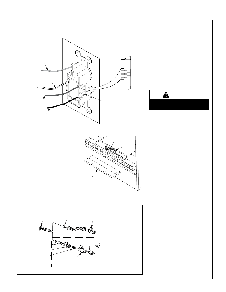
Gas
Valve
3/8" NPT x
Flare Fitting
3/8" Flex Tubing
3/8" Nipple
3/8" Union
3/8" Close
Nipple
3/8" Shut-off Valve
1/2" x 3/8"
Reducer
Gas
Stub
1/2" x 3/8" Flare
Shut-off Valve
Gas Solid Line Connector
Gas Flex Line Connector
*Sediment
Trap
3"
Min
Figure 16 - Gas Connection
Step 6. Connect to Gas Line
Make gas line connections. All codes require a
shut-off valve mounted in the supply line. Figure
16 illustrates two methods for connecting the
gas supply. The flex-line method is acceptable
in the U.S., however, Canadian requirements
vary depending on locality. Installation must be
in compliance with local codes. The gas control
valve is located in the lower control compart-
ment. To access the valve remove the refractory
access panel and set aside (Figure 15 ).
The millivolt control valve has a 3/8"
(10 mm) NPT thread inlet port.
The electronic control valve has a 1/2" (13 mm)
NPT thread inlet port and is fitted with a 1/2" x
3/8" (13 mm x 10 mm) NPT fitting.
Both the millivolt and electronic models are
fitted with a 3" (76 mm) long nipple, 3/8" NPT.
Plan the connections accordingly.
Secure all joints tightly using appropriate
tools and sealing compounds (ensure propane
resistant compounds are used in propane
applications).
Figure 15
Refractory
Access Panel
SIT Valve Shown
Gas Controls
on Valve
Piezo
Igniter
Figure 14
NOTE: Supply wires may be alternatively connected to the outlet using the screw terminals,
however the black supply wire must be wired to a terminal that is opposite (across the outlet) the
point where the white supply wire is connected.
White
(Supply)
Black
(Supply)
Bipolar
Terminal
Screw
120 Vac
60 Hz
Green Wire Ground
Connection
Red
(Supply)
120 Vac
60 Hz
120 Vac
60 Hz
Turn on gas supply and test for gas leaks, us-
ing a gas leak test solution (also referred to as
bubble leak solution).
NOTe: Using a soapy water solution (50%
dish soap, 50% water) is an effective leak test
solution but it is not recommended, because
the soap residue that is left on the pipes/fittings
can result in corrosion over time.
A. Light the appliance (refer to the lighting
instructions label in the control compartment
or in the Homeowner's Care and Operation
Instructions).
b. Brush all joints and connections with the
gas leak test solution to check for leaks. If
bubbles are formed, or gas odor is detected,
turn the gas control knob to the “OFF” posi-
tion. Either tighten or refasten the leaking
connection and retest as described above.
C. When the gas lines are tested and leak free,
be sure to rinse off the leak testing solution.
D. When the gas lines are tested and leak free,
observe the individual tongues of flame on
the burner. Make sure all ports are open and
producing flame evenly across the burner. If
any ports are blocked, or partially blocked,
clean out the ports.
WARNING
Never use an open flame to
check for leaks.
TeST ALL CONNeCTIONS FOR GAS LeAKS
(FACTORY AND FIeLD):