Lenovo RD120 User Manual
Page 23
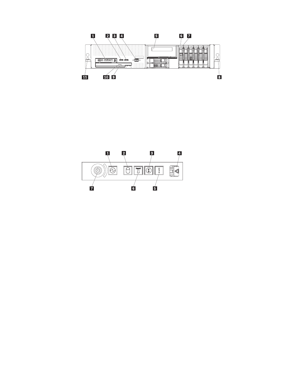
1
Operator
information
panel
7
Hard
disk
drive
status
LED
(amber)
2
USB
connector
8
Rack
release
latch
3
USB
connector
9
CD/DVD
eject
button
4
Video
connector
10
CD/DVD
drive
activity
LED
5
Tape
drive
bay
11
Rack
release
latch
6
Hard
disk
drive
activity
LED
(green)
Operator
information
panel:
This
panel
contains
controls,
LEDs,
and
connectors.
The
following
illustration
shows
the
controls,
LEDs,
and
connectors
on
the
operator
information
panel.
1
Power-on
LED
5
System
error
LED
2
Hard
disk
drive
activity
LED
7
System
locator
LED
3
Information
LED
7
Power-control
button
4
Release
latch
The
following
controls,
LEDs,
and
connectors
are
on
the
operator
information
panel:
v
Power-control
button:
Press
this
button
to
turn
the
server
on
and
off
manually.
A
power-control-button
shield
comes
installed
on
the
server
to
prevent
the
server
from
being
turned
off
accidentally.
v
Power-on
LED:
When
this
LED
is
lit
and
not
flashing,
it
indicates
that
the
server
is
turned
on.
When
this
LED
is
flashing,
it
indicates
that
the
server
is
turned
off
and
still
connected
to
a
power
source.
When
this
LED
is
off,
it
indicates
that
power
is
not
present,
or
the
power
supply
or
the
LED
itself
has
failed.
Note:
If
this
LED
is
off,
it
does
not
mean
that
there
is
no
electrical
power
in
the
server.
The
LED
might
be
burned
out.
To
remove
all
electrical
power
from
the
server,
you
must
disconnect
the
power
cord
from
the
electrical
outlet.
Attention:
In
a
dc
power
environment,
only
trained
service
personnel
other
than
Lenovo
service
technicians
are
authorized
to
connect
or
disconnect
power
to
the
dc
power
supply.
See
the
documentation
that
comes
with
each
dc
power
supply.
v
Hard
disk
drive
activity
LED:
When
this
LED
is
flashing,
it
indicates
that
a
hard
disk
drive
is
in
use.
v
System-locator
LED:
Use
this
LED
to
visually
locate
the
server
among
other
servers.
Chapter
1.
The
ThinkServer
RD120
server
9