Troubleshooting & repair – Lincoln Electric POWER WAVE SVM173-A User Manual
Page 132
TROUBLESHOOTING & REPAIR
F-86
F-86
POWER WAVE 455M/MSTT
13/14
OR
17/18
NYLON
SCREW
(2X)
19+
20-
11/12
OR
15/16
SWITCH
BOARD
MOLEX PLUG
MOUNTING
SCREW (4X)
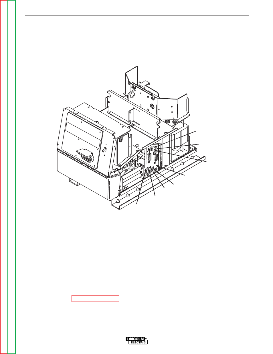
FIGURE F.28 – SWITCH BOARD AND FILTER CAPACITOR REMOVAL AND REPLACEMENT
SWITCH BOARD AND FILTER CAPACITOR
REMOVAL AND REPLACEMENT (CONTINUED)
REMOVAL PROCEDURE
NOTE: Observe all static electricity precau-
tions.
Lead and plug references below use a slash (/)
to indicate machine right side/left side wire
number differences.
1. Remove input power to the Power Wave
455.
2. Using the 3/8” nut driver, remove the case
top.
3. Perform the Capacitor Discharge proce-
dure.
4. Using the 5/16” nut driver, remove the three
screws mounting the plastic high voltage
protective shield. Remove the shield.
5. Remove molex plug J40/J50 from the top of
the switch board. Refer to Figure F.28.
6. Remove the mylar insulating shield covering
leads 13/14 or 17/18. Cut the cable tie.