Warning, Safety edge layout illustration – Linear SWR User Manual
Page 23
SWR
• SWC • SWD Swing Gate Operator Installation Guide
- 21 -
227965 Revision X22 8-11-2011
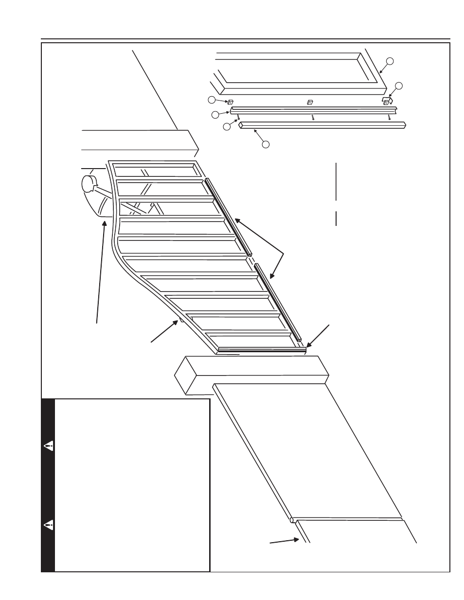
Safety Edge Layout Illustration
R
ECEIVE
R
IN
S
IDE
G
ATE OPE
R
ATO
R
G
ATE ED
G
E
T
R
AN
S
MITTE
R
S
EPA
R
ATE PEDE
S
T
R
IAN
G
ATE
R
EQUI
R
ED
7FT. MINIMUM DI
S
TANCE
AWAY F
R
OM
G
ATE
ED
G
E MOUNTED ON
LEADIN
G
OUT
S
IDE ED
G
E
OF
G
ATE
ED
G
E
S
MOUNTED AC
R
O
SS
B
OTTOM OF
G
ATE
WI
R
E ED
G
E
S
S
HOWN TO THE CLO
S
E O
BS
T
R
UCTION INPUT ONLY
ITEM
DE
S
C
R
IPTION
1
G
ATE (
R
EFE
R
ENCE ONLY)
2 ED
G
E
3 ED
G
E EXT
R
U
S
ION
4
S
PACE
RS
(
3)
5
8-
32 X 1"
S
C
R
EW
S
(
3)
6
R
ETAININ
G
BR
ACKET
R
EVE
RS
IN
G
ED
G
E
A
SS
EM
B
LY CLO
S
E-UP
5
1
2
3
4
6
W
ARNING
One or more contact sensors shall be located on the
inside and outside leading edge of a swing gate.
Additionally
, if the bottom edge of a swing gate is
greater than six inches (152 mm) above the ground
at any point in its arc of travel, one or more contact
sensors shall be located on the bottom edge.
A hardwired contact sensor shall be located and its
wiring arranged so that the communication between
the sensor and the gate operator is not subjected to
mechanical damage.
A wireless contact sensor such as one that transmits
radio frequency (RF) signals to the gate operator for
entrapment protection functions shall be located where
the transmission of the signals are not obstructed or
impeded by building structures, natural landscaping
or similar obstruction. A wireless contact sensor shall
function under the intended end-use conditions.