Troubleshooting the millivolt gas control system – Lennox Hearth EDVI25 User Manual
Page 20
0
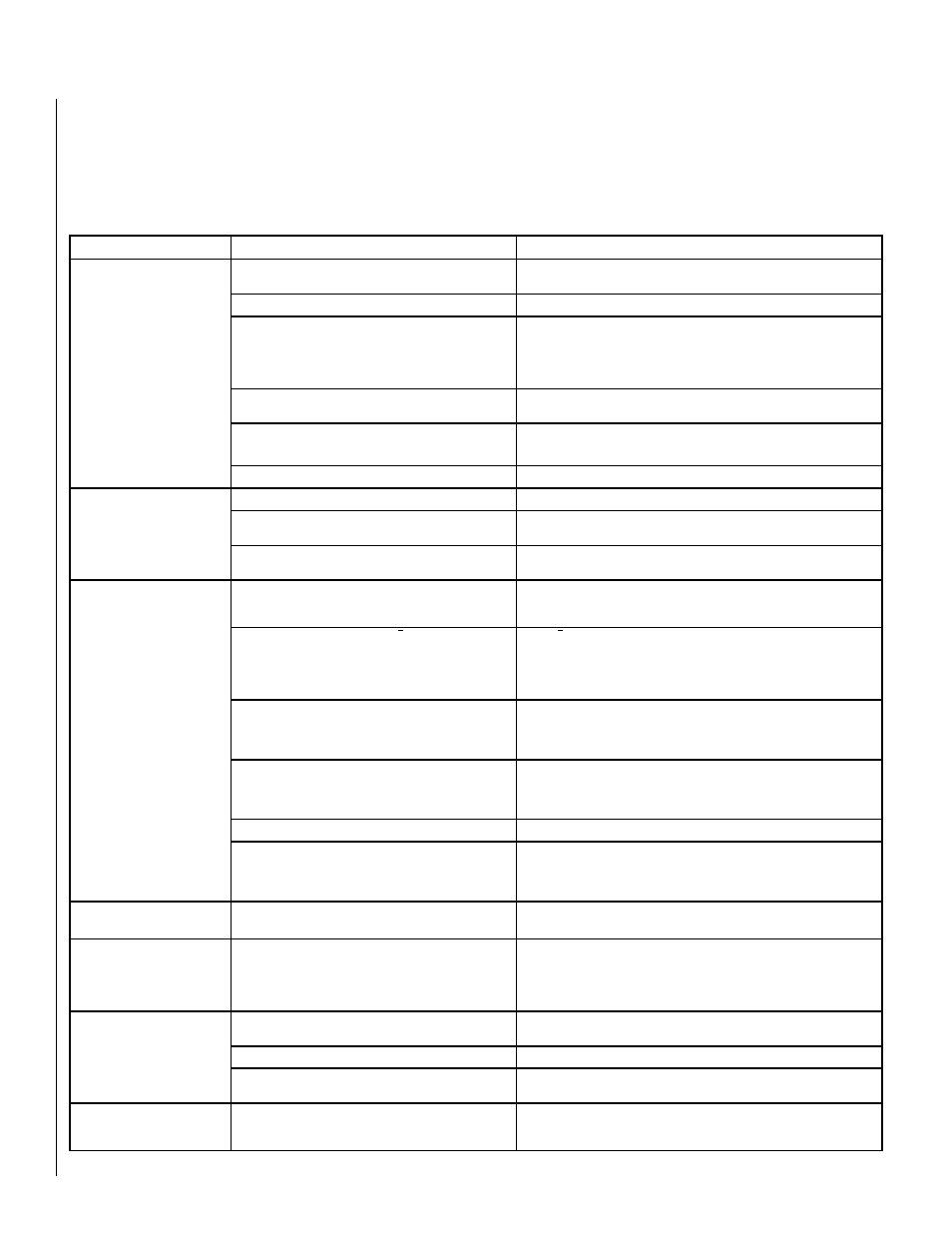
TROUBLESHOOTING THE MILLIVOLT GAS CONTROL SYSTEM
Note: Before troubleshooting the gas control system, be sure external gas shut off valve (located at gas supply inlet) is
in the “ON” position.
Important: Valve system troubleshooting should only be accomplished by a qualified service technician.
SYMPTOM
POSSIBLE CAUSES
CORRECTIVE ACTION
1) Spark igniter will not light
pilot after repeated triggering of
igniter button.
WARNING: IF THE PILOT WILL
NOT LIGHT AFTER ONE MINUTE
OF ATTEMPTING, WAIT FOR AT
LEAST FIVE MINUTES FOR GAS
TO CLEAR BEFORE ATTEMPTING
AGAIN.
A. Electrode wire (at Piezo Igniter) not pushed completely
on.
• Check connection
B. Piezo igniter is defective
• Replace piezo igniter
C. Defective or misaligned electrode at pilot (spark at
electrode)
• Using a match, light pilot. If pilot lights, turn off pilot and trigger the igniter
button again. If pilot lights, an improper gas mixture caused the bad lighting
and a longer purge period is recommended. If pilot will not light – check gap at
electrode and pilot – It should be between 1/8” and 3/16.” If the gap is out of this
range, adjust the gap or replace the pilot assembly. (Page 13, Figure 38)
D. Incorrect lighting procedure
• Carefully follow the lighting instructions on Pages 16 &17 or as found in
the insert control compartment.
E. Gas supply problem
• Check for multiple gas shut-offs. Check gas supply lines.· Check inlet gas
pressure. It should be within the limits as marked on the rating plate.
F. Pilot orifice plugged
• Clean or replace pilot orifice
) Pilot will not stay lit after
carefully following the lighting
instructions.
A. Thermocouple is not firmly connected to control valve
• Check connection at valve
B. Pilot flame is not directed to top of thermocouple
• Ensure thermocouple is fully inserted into pilot assembly. Clean and/or adjust
pilot for maximum flame impingement on thermocouple if necessary.
C. Thermocouple is defective. The millivolt production should
be a minimum of 14 MV with pilot only.
• Replace thermocouple
3) Pilot flame stays lit, but
main burner will not light. (Valve
pilot/on/off knob is in ON position,
on/off switch, wall thermostat or
remote control is set to ON).
Read important note below.
IMPORTANT NOTE: If an
optional Remote Switch*
is used for burner opera-
tion and if the standard
burner OFF/ON switch is
still installed on appli-
ance, it must be in the
"OFF" position.
A. Burner control switch (on/off switch, wall thermostat or
remote control) is in “OFF” position; or thermostat (if installed)
is set to a temperature setting that is too low.
• Turn burner on/off switch on and/or refer to instructions provided with
optional thermostat or remote control, if applicable.
B. Electrical wiring is damaged or poorly connected or
remote switch is defective.
• Check wall switch and wires for proper connections. Refer to Millivolt Wiring
Diagram (Page 14, Figure 41). Jump the wire across terminals at the wall
switch, if the burner comes on, replace the defective wall switch. If okay, jumper
the wires across the wall switch wires at the valve. If the burner comes on,
wires are faulty or connections are bad.
C. One of the following components may be defective:
burner control switch, thermostat or thermopile. Thermopile:
Millivolt production should be a minimum of 325 MV with
pilot only.
• Refer to Millivolt Wiring Diagram (Page 14, Figure 41). Electrically bypass
components one at a time and replace defective item.
D. Thermopile may not be generating sufficient mil-
livolts
• Check thermopile with millivolt meter. Take reading at thermopile ter-
minals of gas valve. It should read 325 millivolts minimum with optional
wall switch “OFF.” Replace faulty thermopile if reading is below specified
minimum.
E. Plugged burner orifice
heck burner orifice for blockage and remove.
F. OFF/ON Switch & Remote Switch* are in the "ON"
position resulting in excessive resistance
When turning on the burner using a Remote Switch,* ensure that the
standard OFF/ON Switch is in the "OFF" position. If both switches are in
the ON position, it may result in excessive resistance (& millivolt drainage)
and the burner may not come on.
4) Frequent pilot/burner outage
problem
A. Pilot flame may be too low or blowing (high) causing the
pilot/valve safety to drop out.
• Clean and/or adjust pilot flame for maximum flame impingement on ther-
mocouple (Page 13, Figure 38).
5) Smell of gas
A. Pilot, gas supply system, or pilot & burner adjustment
screws on valve may be leaking. FOLLOW INSTRUCTIONS
ON THE COVER OF THIS MANUAL
• WARNING: NEVER USE AN OPEN FLAME TO CHECK FOR LEAKS.
After the gas company or fire department has given clearance to re-enter the
dwelling, have a qualified technician test all gas joints from the gas meter to
the gas heater regulator for leaks using a gas leak test solution (also referred
to as bubble leak solution).
6) A thin coating of black soot
forms on the window. NOTE: See
Page 5, Glass Cleaning.
A. Burner primary air inlet is restricted or blocked
• Ensure all openings (fresh air inlets) in the insert are free from dust and
debris. Recheck these areas periodically.
B. Flames make contact with logs or other surfaces
• Ensure ceramic logs are in their correct positions.
C. Improper venting
• Check for flue blockage, disconnected flue, improper installation. Make
appropriate corrections.
7) A white coating forms on
windows, logs, and/or inside
walls of firebox.
A. Residues/impurities being burned off or impurities in the
fuel
• Follow cleaning guidelines outlined in the MAINTENANCE section of this
manual.
*Optional Remote Switch kits: wall switch, wall thermostat or remote control.