Accessories – Lincoln Electric INVERTEC V350-PRO SVM152-A User Manual
Page 24
C-8
C-8
V350-PRO
ACCESSORIES
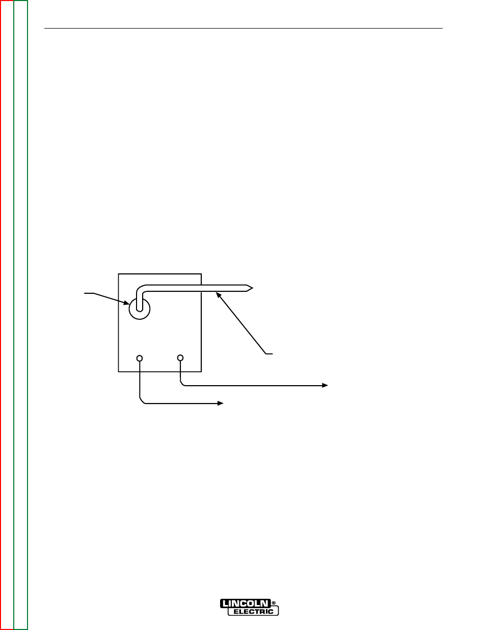
CONNECTION OF THE LN-742 TO THE
V350-PRO (SEE FIGURE C.7)
NOTE: AN LN-7 CAN ONLY BE USED WITH A FAC-
TORY OR “CE” VERSION OF THE V350-PRO.
1. Remove input power to the V350-PRO.
2. Connect the electrode cable from the LN-742 to
the “+” terminal of the welder. Connect the work
cable to the “-” terminal of the welder.
NOTE: Figure C.7 shows the electrode connected
for positive polarity. To change polarity, shut the
welder off and reverse the electrode and work
cables at the output terminals.
NOTE: Welding cable must be sized for current
and duty cycle of application.
3. Connect the K591 control cable to the 24/42VAC
14 pin amphenol on the back of the V350-PRO
and the input cable plug on the LN-742.
4. Set the “VOLTMETER” switch to “+” or “-”
depending on the polarity chosen.
5. Set the “MODE” to the “CV-WIRE” position..
6. Set “CONTROL SELECT” to “LOCAL”.
7. Place the “WELD TERMINALS SELECT” in the
“REMOTE” position.
8. Adjust wire feed speed at the LN-742.
9. Set the “ARC” control at “0” initially and adjust to
suit.
+ -
14 PIN
AMPHENOL
TO LN-742 INPUT
CABLE PLUG
TO WORK
K591 CONTROL CABLE
ELECTRODE CABLE
TO WIRE FEED UNIT
(24/42VAC)
AT REAR OF
MACHINE
Figure C.7 V350-PRO/LN-742 Connection Diagram