0 controls and indicators, Figure 16 display and status indicators, Ontrols – Liebert UPS Systems PSI XR User Manual
Page 18: Ndicators, Table 2, Display and status indicators function, legend
Controls and Indicators
14
4.0
C
ONTROLS
AND
I
NDICATORS
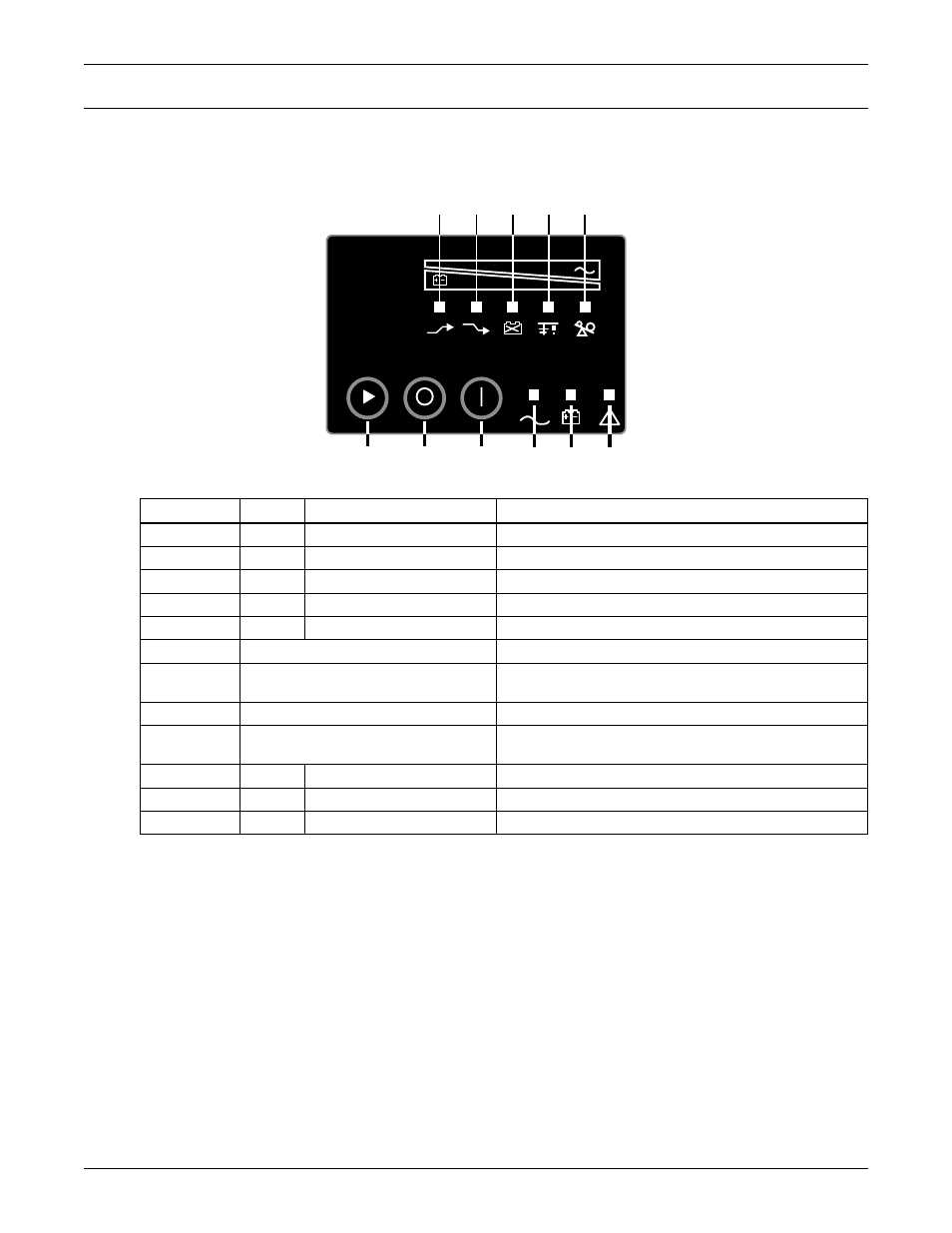
Buttons on the front panel display control the Liebert PSI XR. Eight LEDs indicate the UPS’s status.
Refer to Figure 16 and Table 2.
Figure 16 Display and status indicators
Table 2
Display and status indicators function, legend
Item
Name
Status Indicators
Description
1
LED 1
AVR Boost
UPS Operation in AVR Boost Mode
2
LED 2
AVR Buck
UPS Operation in AVR Buck Mode
3
LED 3
Battery Condition
Battery Fault/Weak
4
LED 4
Grounding/Site Wiring Fault
UPS Grounding/Site Wiring Fault
5
LED 5
Overload
UPS Overload
1 to 5
Load/Battery Level
Indicate Load/Battery Level
6
Status Change Button
Switches Display from Load Level Indicators
to Battery Level Indicators
7
OFF Button
UPS Off
8
ON Button
Turn on UPS, Manual Self-Diagnostic (Normal Mode),
Silence Alarm (Battery Mode)
9
LED 9
Normal Mode
UPS Operation in Normal Mode
10
LED 10
Battery Mode
UPS Operation in Battery Mode
11
LED 11
UPS Fault
UPS Fault
Load Level
Battery Level
1
2
3
4
5
6
7
8
9
10
11