He series, Lass, Ivision – Lightolier Emergency Lighting HE Series User Manual
Page 2: Mergency, Ighting
HE Series
C
LASS
I D
IVISION
2 E
MERGENCY
L
IGHTING
Page 2 of 2
Philips Lightolier
e: [email protected]
t: (508)
679-8131
w: www.lightolier.com
HE Series August 4, 2011
Specifications are subject to change without notice.
© Koninklijke Philips Electronics N.V., 2011. All rights reserved.
Job Information
Type:
Ordering Information
Series
HE1 = 6 VDC
Class I Div. 2
Emergency Lighting
Unit
HE2 = 12 VDC
Class I Div. 2
Emergency Lighting
Unit
6 V Lead Calcium
25L = 25 Watt Unit
50L = 50 Watt Unit
6 V Nickel Calcium
25N = 25 Watt Unit
50N = 50 Watt Unit
75N = 75 Watt Unit
12 V Lead Calcium
25L = 25 Watt Unit
50L = 50 Watt Unit
100L = 100 Watt Unit
125L = 125 Watt Unit
12 V Nickel Calcium
25N = 25 Watt Unit
50N = 50 Watt Unit
75N = 75 Watt Unit
100N = 100 Watt Unit
125N = 125 Watt Unit
150N = 150 Watt Unit
Battery/DC Voltage
# of Heads
Blank = No Lamp Heads
1 = One Lamp Head
2 = Two Lamp Heads
3 = Three Lamp Heads
Lamp Heads
6 V Tungsten
HT8 = 8 Watts
HT12 = 12 Watts
HT18 = 18 Watts
HT25 = 25 Watts
6 V Halogen
HH8 = 8 Watts
HH12 = 12 Watts
12 V Tungsten
HT12 = 12 Watts
HT18 = 18 Watts
HT25 = 25 Watts
12 V Halogen
HH8 = 8 Watts
HH12 = 12 Watts
SD2 = Diagnostic
Electronics
Model Designator
1
Optics
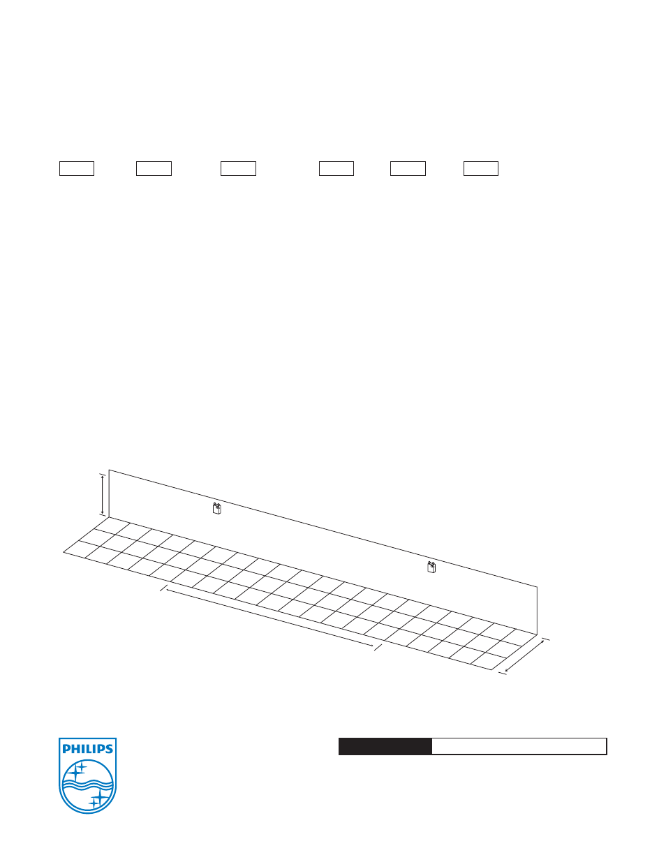
Wall Mounted 7.5' AFF, 12 V 12 W Halogen Lamp Heads Represented
1 FC Average
Note
1) Some option combinations may impact
UL listing. Consult factory for specifications.
7.5 ft.
30 ft.
9 ft.
Average initial footcandles at floor = 1.12
Maximum initial footcandles at floor = 4.9
Minimum initial footcandles at floor = 0.2
Maximum to minimum ratio = 24.50
* The optics layout shown is intended to be used as reference only. Standard reflectances used were 80/50/20. Lightolier is not responsible for site specific conditions that
may alter the results.
.2
.3
.2
.8
1.3
.4
2.7
3.1
.6
2.2
2.1
.5
.9
.8
.5
1.0
.8
.5
2.3
1.9
.5
2.7
3.3
.6
.8
1.3
.5
.2
.3
.2
.2
.3
.2
.8
1.3
.4
2.8
3.1
.6
2.2
2.0
.5
.9
.8
.5
.9
.7
.5
2.4
1.9
.5
2.6
3.2
.6
.7
1.3
.4
.2
.2
.2
SD2
A = Ammeter
EX = Special Input Transformer (specify
voltage & frequency)
T = Self-Testing Diagnostics
TA = Audible Self-Testing Diagnostics
TD = Time Delay (15 minutes)
V = Voltmeter
Factory Installed Options
1
Accessories (order as a separate item)
SDREMOTE = Infrared Remote Test
Device
WG = Wire Guard