Rack, Peration – Lindy Carbon Monoxide Alarm User Manual
Page 22
O
PERATION
O
PERATION
4
Rack
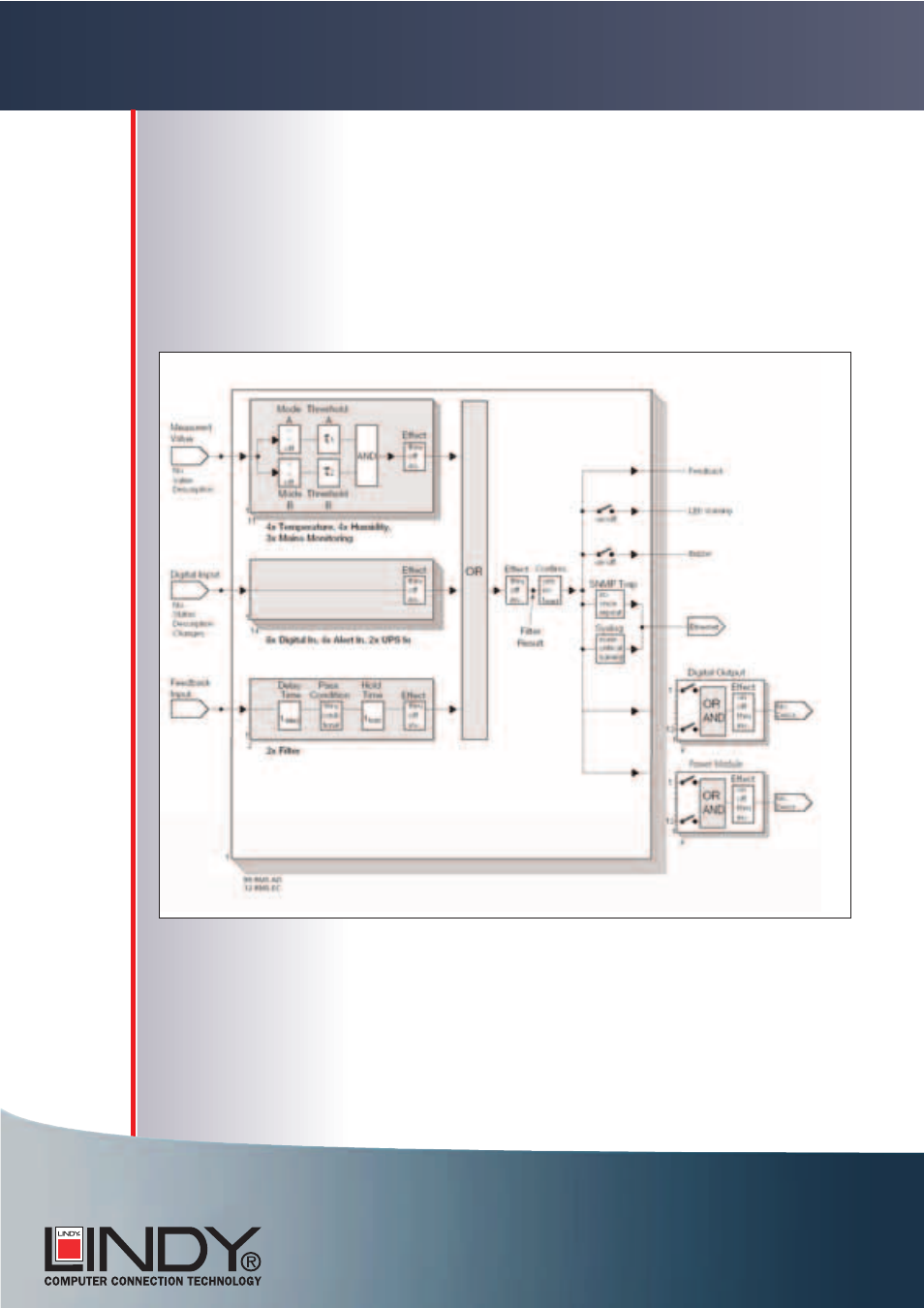
Block diagram
The signals applied at the physical input terminals (left) are combined in
a complex filter structure (centre). The resulting filter result can then be
supplied for switching and signalling purposes at physical output termi-
nals (right) or be used to influence other filters (feedback).
Method of operation and configuration options of the filters. (> 4.9).