Important – Lennox International Inc. o23v User Manual
Page 7
Page 7
B−Burner Control (A3)
All O23V units are equipped with a burner control R7184B
manufactured by Honeywell. The burner control, along with
the matching cad cell, proves flame and controls the burner.
An LED on the control shows unit status. See table 4 for status
codes. After the cad cell closes a circuit to the burner control,
the burner control de−energizes the safety switch heater to al-
low the unit to operate normally. When there is a call for heat
the control performs a 2 to 6 second delay safety check. Once
this is established a 15 second pre−purge will follow. The valve
then opens for a 15 second trial for ignition. If flame is not
sensed during the 15 second trial, the control shuts down and
must be manually re−set. After three consecutive lockouts the
control goes into restricted lockout. Once flame is established
after 10 seconds of run time, the ignitor is de−energized.
If flame is lost during the heat cycle the control will shut
down the burner and begin a 60 second recycle delay. Af-
ter 60 seconds the control repeats the ignition process. If
flame is lost three consecutive times during a single ther-
mostat demand the control goes into restricted lockout.
Reset button
If the control locks out three consecutive times the control
will go into restricted lockout. To reset control hold down
the reset button for 30 seconds until the LED flashes twice.
At any time the burner motor is energized, press and hold
the reset button to disable the burner. The burner will re-
main disabled as long as the reset button is held down and
return to operation once the button is released.
TABLE 4
LED
STATUS
On
Flame sensed
Off
Flame not sensed
Flashing
(1/2 sec on1/2 sec off)
Lockout /
Restricted Lockout
Flashing
(2 sec on 2 sec off)
Recycle
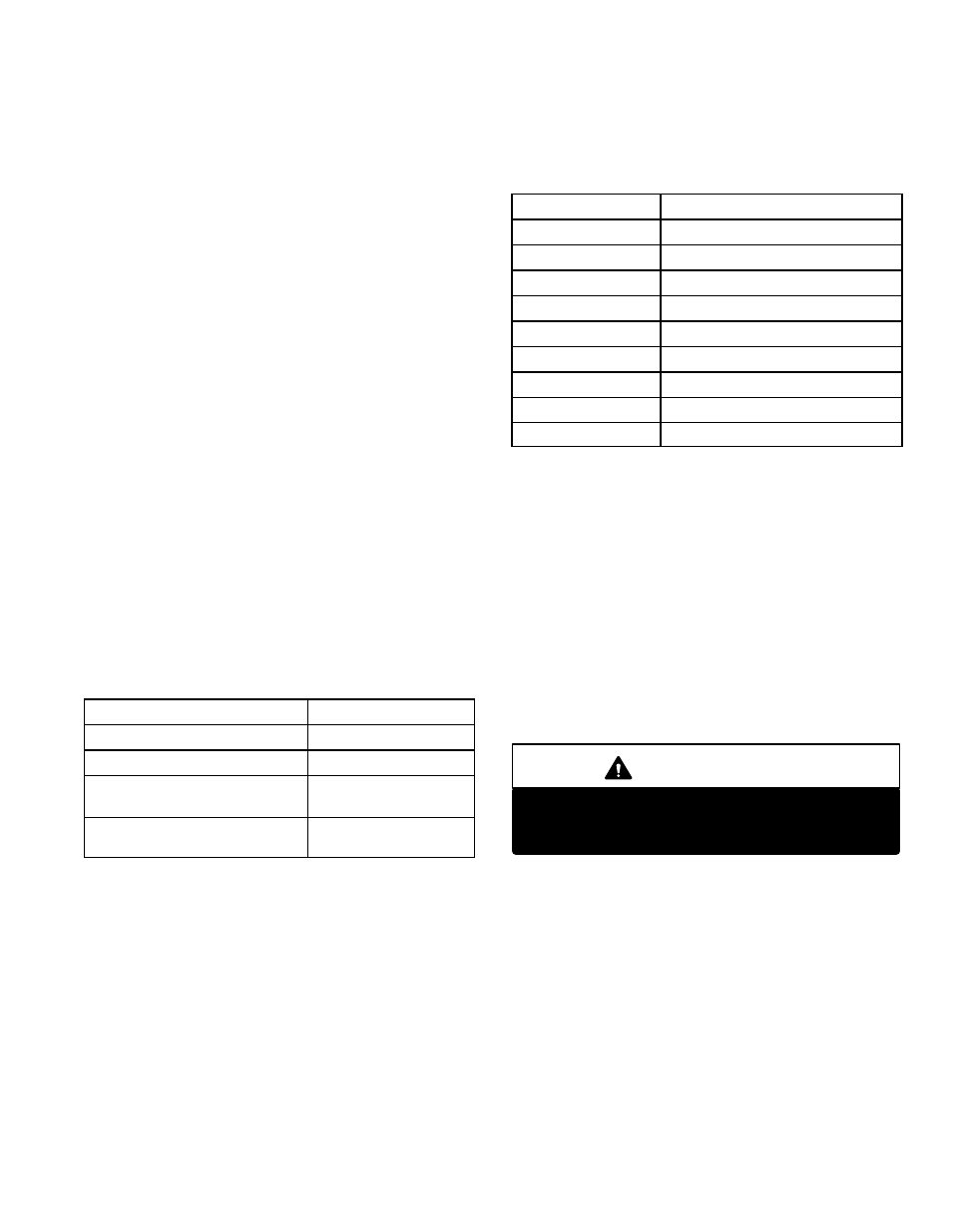
C−Control ST9103A (A15)
Control ST9103A manufactured by Honeywell, is a
printed circuit board which monitors limit operation and
oil burner operation. Line voltage and thermostat con-
nections are made on this control. See table 5 for termi-
nal designations.
TABLE 5
J58 Pin #
Function
1
Limit S10
2
L1 120V
3
24V
4
L2 Common
5
Jumpered to Pin 4
6
24V
7
Burner Motor
8
Jumpered to Pin 7
9
Limit S21 (if used)
D−Transformer (T1)
Transformer T1 provides power to the low voltage sec-
tion of the unit. Transformers are rated 40VA with a
120V primary and 24V secondary.
E−Primary Limit Control (S10)
The primary limit on all O23V units, is located on the vesti-
bule panel. When excess heat is sensed in the heat ex-
changer, the limit will open. If the limit is tripped, 24 volt
power to terminal R" on the indoor thermostat is lost and the
unit shuts down but the indoor blower continues to run. The
limit automatically resets when unit temperature returns to
normal. The switch is factory set and cannot be adjusted. The
setpoint is printed on the face plate of the limit.
IMPORTANT
If using programmable thermostat, be sure to use
a type of thermostat that retains its memory in
event of a power loss.