Warning, Caution – Lennox International Inc. o23v User Manual
Page 12
Page 12
B−Venting Considerations
WARNING
Combustion air openings in front of the furnace
must be kept free of obstructions. Any obstruction
will cause improper burner operation and may re-
sult in a fire hazard or injury.
WARNING
The barometric shall be in the same atmospheric
pressure zone as the combustion air inlet to the
furnace. Deviation from this practice will cause im-
proper burner operation and may result in a fire
hazard or injury.
CAUTION
Do not store combustible materials near the fur-
nace or supply air ducts. The material (such as
paint, motor oil, gasoline, paint thinner, etc.) may
ignite by spontaneous combustion creating a fire
hazard.
WARNING
This furnace is certified for use with type L" vent.
B" vent must not be used with oil furnaces.
NOTE−Oil burning equipment may be vented into an ap-
proved masonry chimney or type L vent. (Type L vent is
similar in construction to type B gas vent except it carries a
higher temperature rating and is constructed with an inner
liner of stainless steel rather than aluminum).
Prior to installation of unit, make a thorough inspection of the
chimney to determine whether repairs are necessary. Make
sure the chimney is properly constructed and sized accord-
ing to the requirements of the National Fire Protection Asso-
ciation. The smallest dimensions of the chimney should be
at least equal to the diameter of the furnace vent connector.
Make sure the chimney will produce a steady draft sufficient
to remove all the products of combustion from the furnace.
A draft of at least 0.04" w.c. (9.9 Pa) is required during burn-
er operation.
1− Local building codes may have more stringent instal-
lation requirements and should be consulted before
installation of unit.
2− The vent connector should be as short as possible to
do the job.
3− The vent connector should not be smaller than the
outlet diameter of the vent outlet of the furnace.
4− Pipe should be at least 24 gauge galvanized.
5− Single wall vent pipe should not run outside or through
any unconditioned space.
6− Chimney should extend 3 feet (0.9 m) above the high-
est point where the vent passes through the roof, and 2
feet (0.6 m) higher than any portion of a building within
a horizontal distance of 10 feet (3 m).
7− The vent must not pass through a floor or ceiling. Clear-
ances to single wall vent pipe should be no less than 6"
(152 mm); more if local codes require it.
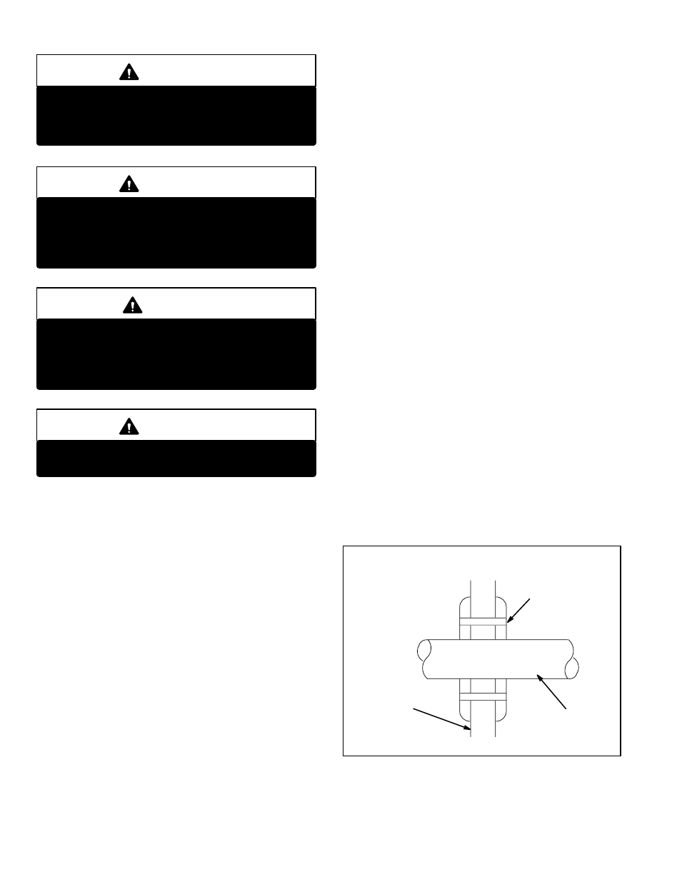
8− The vent may pass through a wall where provisions have
been made for a thimble as specified in the Standards of
the National Board of Fire Underwriters. See figure 7.
9− The vent pipe should slope upward toward the chim-
ney on horizontal run at least 1/4 inch (6 mm) to the
foot (0.3 m) and should be supported by something
other than the furnace, such as isolation hangers. See
figure 8.
10− Extend the vent pipe into the chimney so that it is flush
with the inside of the vent liner. Seal the joint between
the pipe and the liner.
11− The furnace shall be connected to a factory built
chimney or vent complying with a recognized stan-
dard, or masonry or concrete chimney lined with a
lining material acceptable to the authority having
jurisdiction.
WALL THIMBLE
FIGURE 7
THIMBLE
VENT PIPE
COMBUSTIBLE
WALL