Liebert GXT2 - 3X1 User Manual
Page 38
38 Appendix 2 Communication Port Description
E1-20010329-C-1.0
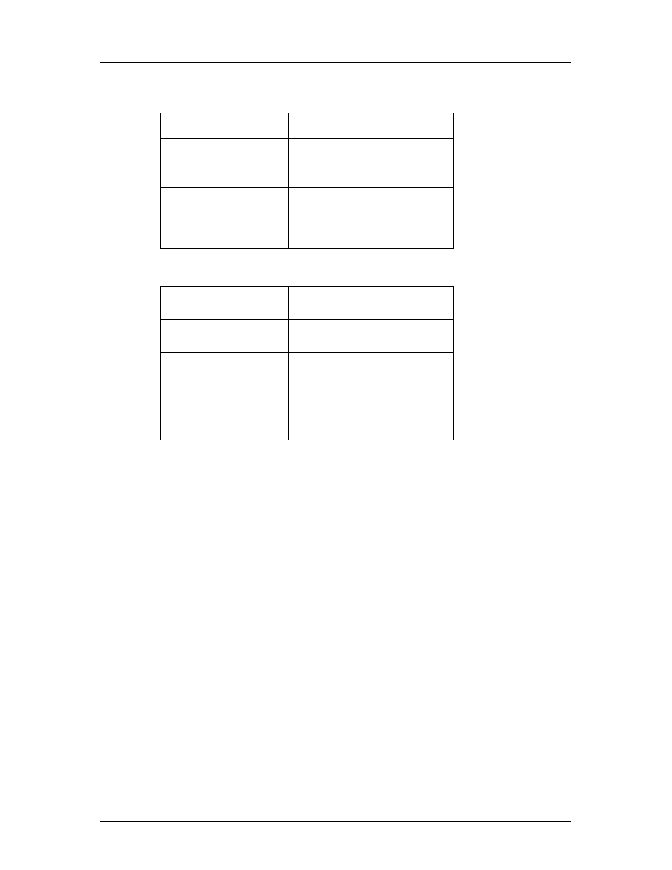
Connection
alarm Signal
Pin . 1/2/3 (normally open /common
normally close)
failure Signal
Pin . 4/5/6 (normally open/common
/normally close)
Bypass mode signal
Pin . 7/8/9 (normally open/common
/normally close)
battery low Signal
Pin . 10/11/12 (normally open/
common / normally close)
Shutdown Signal
Pin .14/15th Pin(short circuited
normally , UPS shutdown when open
circuit )
Connection of relays
alarm Signal Relay
In normal state, Pin . 2/3 are short
circuited, Pin . 1/2 pins are short
circuited when alarm is activated .
failure Signal Relay
In normal state, Pin . 5/6 are short
circuited, No. 4/5 pins are short
circuited when signal is activated.
Bypass mode Signal Relay
In normal state, Pin . 8/9 are short
circuited, Pin .7/8 are short circuited
when signal is activated.
battery low Signal Relay
In normal state, Pin . 11/12 are short
circuited_, Pin . 10/11 are short
circuited when signal is activated .
Shutdown Signal Relay
Invalid when pin 14/15 are open
circuit , UPS will shutdown .
Relay Contact Capacity
250VAC 2A or 30VDC 2A