English – KTM 400 User Manual
Page 24
ENGLISH
23
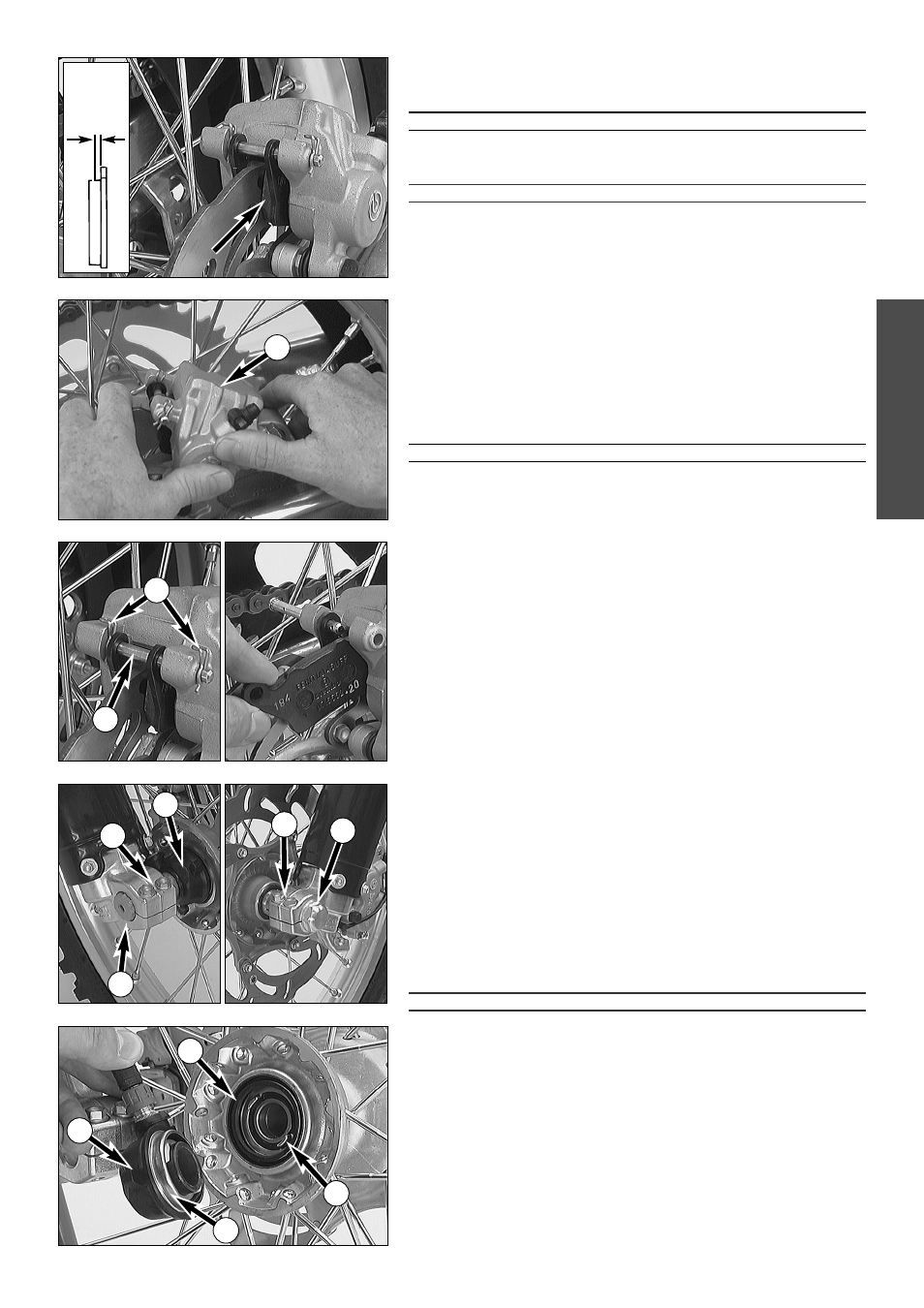
Checking the rear brake pads
The brake pads can be inspected from the rear. The thickness of the linings
may not be less than 1 mm (0.04 in).
ƽ
WARNING
ƽ
A
T THEIR MOST WORN POINT BRAKE PAD LININGS SHOULD NOT BE THINNER THAN
1
MM
,
OTHERWISE THEY COULD LEAD TO BRAKE FAILURE
. F
OR YOUR OWN SAFETY
DON
’
T PUT OFF HAVING YOUR BRAKE PADS CHANGED
.
!
CAUTION
!
I
F THE BRAKE PADS ARE REPLACED TOO LATE SO THAT THE LINING IS PARTLY OR ENTIRELY
WORN
,
THE STEEL COMPONENTS OF THE BRAKE PAD WILL RUB AGAINST THE BRAKE DISC
,
THEREBY IMPARING THE BRAKING EFFECT AND DESTROYING THE BRAKE DISC
.
Replacing the rear brake pads *
Push the brake caliper
1
toward the chain wheel in order to move the
brake piston into its basic position. Remove clips
2
, pull out the bolt
3
,
and remove the brake pads. Thoroughly clean the brake caliper with com-
pressed air and check the sleeves of the guide bolts for damage.
Insert the left brake pad into the brake caliper and secure it with the bolt.
Insert the right brake pad and push the bolt
3
into the brake caliper up to
the stop. Reattach clips
2
.
ƽ
WARNING
ƽ
– I
T IS VERY IMPORTANT TO KEEP THE BRAKE DISK FREE FROM OIL AND FATTY MATTERS
.
O
THERWISE
,
THE BRAKING EFFECT WOULD BE STRONGLY REDUCED
.
– A
FTER ASSEMBLY
,
CHECK IF CLIPS HAVE BEEN FITTED CORRECTLY
.
– H
AVING PERFORMED ANY WORK ON THE BRAKING SYSTEM
,
ONE MUST ALWAYS
ACTUATE THE HAND BRAKE LEVER OR FOOT BRAKE LEVER
,
RESPECTIVELY SO AS TO
ENSURE THAT THE BRAKE PADS WILL LIE AGAINST THE BRAKE DISK AND THE PRESSURE
POINT IS ESTABLISHED
.
Dismounting and mounting the front wheel
To remove the front wheel, jack the motorcycle up on its frame so that the
front wheel no longer touches the ground.
Loosen the 2 clamping screws
5
on the left side of the fork fists.
Loosen and remove the collar nut
4
., loosen the clamping screews
6
on
the right side
6
of the fork fist
Hold the front wheel, pull out the wheel spindle
7
.
NOTE: The wheel spindle can be easily removed if you slightly revolve it
with a ring span-ner (SW 21 mm) or a hexagon socket screw key (6 mm).
Remove front wheel carefully from the fork and take the speedometer drive
8
off the hub.
NOTE: Models with a digital speedometer have a distance bushing instead
of the speed-ometer drive.
!
CAUTION
!
– D
O NOT OPERATE THE HAND BRAKE WHEN THE FRONT WHEEL HAS BEEN
DISMOUNTED
.
– M
AKE SURE THE BRAKE DISC IS ALWAYS ON TOP WHEN YOU LAY DOWN THE WHEEL
,
OTHERWISE THE BRAKE DISC CAN BE DAMAGED
.
Prior to mounting the front wheel, clean and grease sealing ring
9
and
running surface
bk
at the speedometer drive.
Lift front wheel into fork, and insert speedometer drive or distance sleeve
into hub. Make sure that the driving tabs
bl
engage with the slot of the
drive.
Position front wheel and speedometer drive or distance sleeve and mount
wheel spindle.
min.
1 mm
2
4
5
1
3
6
7
8
8
9
10
11