33 — connecting cables to terminals, Connector function guide – Kenwood KDC-PS909 User Manual
Page 33
— 33 —
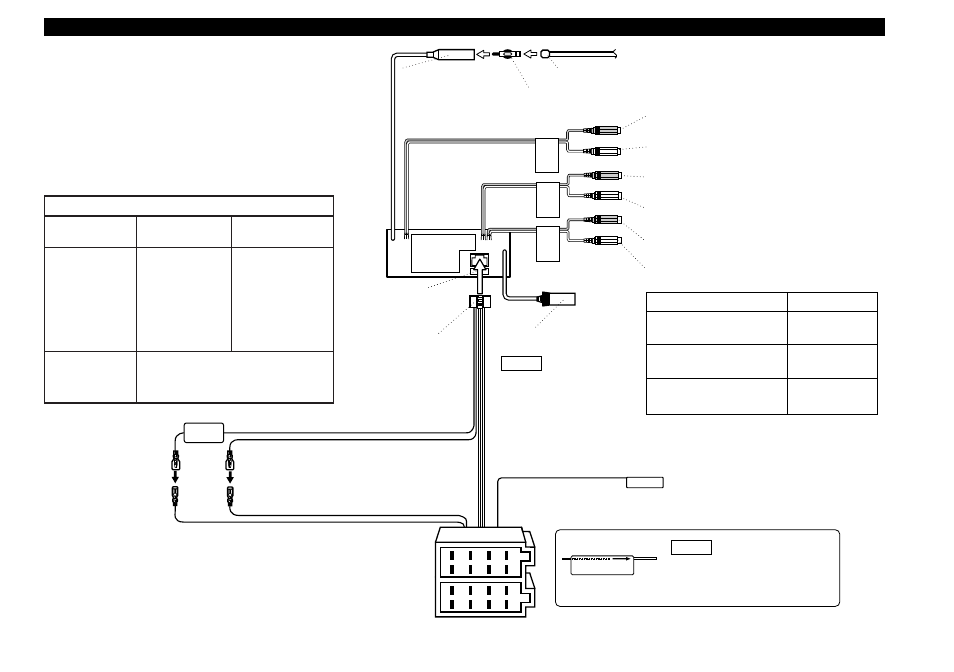
Connecting Cables to Terminals
P.CONT.OUT
1
2
3
4
5
6
7
8
1
2
3
4
5
6
7
8
F
R
O
N
T
R
E
A
R
N
O
N
-F
A
D
Fuse
KENWOOD disc changer/
DAB control input
Wiring harness
(Accessory1)
Ignition cable (Red)
Battery cable (Yellow)
If no connections are made, do
not let the cable come out
from the tab.
NOTE
To connect the Disc
changer or DAB unit,
consult each manual.
NOTE
Connect either to the power control
terminal when using the optional power
amplifier, or to the antenna control
terminal in the vehicle.
UNBALANCED
BALANCED
Left
Left
-
Right
Right
-
Left
Left
+
Right
Right
+
Left
Monaural
+
Right
Monaural
-
FRONT
REAR
NON-FADING
Rear left/
Balanced left+ output (White)
Rear right/
Balanced right+ output (Red)
Front left/
Balanced left- output (White)
Front right/
Balanced right- output (Red)
Non-fading left/
Balanced monaural+ output (White)
Non-fading right/
Balanced monaural- output (Red)
Power control/ Motor
antenna control cable
(Blue/White)
A–7 Pin (Red)
A–4 Pin (Yellow)
Connector B
Connector A
FM/AM antenna input
Antenna Cord (ISO)
Antenna Conversion Adaptor (ISO–JASO) (Accessory4)
Connector Function Guide
Pin Numbers for
ISO Connectors
Cable Colour
Functions
External Power
Connector
A–4
A–5
A–7
A–8
Speaker
Connector
B
Yellow
Blue/White
Red
Black
Battery
Power Control
Ignition (ACC)
Earth (Ground)
Connection
Not used
(Not used)