Kenwood TRK-750 User Manual
Page 2
REPEATER OPERATION
Note:
Please consult your dealer for programming the repeater.
When power is applied to the unit, the Power indicator
lights:
•
Green when using the main DC jack.
•
Red when using the Backup terminal.
Rotate the VOLUME control to adjust the volume.
The BUSY indicator lights green while receiving a signal
and the TX indicator lights red while transmitting.
q
q
q
q
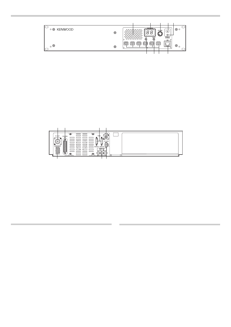
q Speaker
w
w
w
w
w CH/STATUS Display
Two, 7-segment digits display the channel number
or status.
e
e
e
e
e VOLUME control
Rotate to adjust the volume.
r
r
r
r
r DC SOURCE switch
t
t
t
t
t Power indicator
Lights green when power is applied from the DC
13.6V jack (DC 13.2V jack on E type versions).
Lights red when power is applied from the BACK
UP battery terminal.
y
y
y
y
y MIC jack
Connect a microphone to this 8-pin modular jack.
u
u
u
u
u Programmable Function keys
Press these keys to activate their programmable
functions.
i
i
i
i
i BUSY indicator
Lights green while a signal is being received.
o
o
o
o
o TX indicator
Lights red while transmitting.
■
Rear Panel
q
q
q
q
q TX OUT jack
Connect a TX antenna or a duplexer to this recep-
tacle.
w
w
w
w
w CONTROL I/O jack
Connect an external programming device or re-
peater controller to this DB-25 interface.
e
e
e
e
e FUSE
Insert 15 A blade fuses into these fuse holders.
r
r
r
r
r RX IN jack
Connect a RX antenna or a duplexer to this BNC
receptacle.
t
t
t
t
t DC 13.6V (K type) / DC 13.2V (E type) jack
Connect a 13.6 V (K type) or 13.2 V (E type) DC
power supply to this jack.
y
y
y
y
y BACKUP battery terminal
u
u
u
u
u TEST/SPKR jack
Test input/output jack. Connect an external
speaker to this jack.
TRANSCEIVER OPERATION
■
Receive
Adjust the volume to your desired level. You may need
to readjust the volume when you receive a message
from your dispatcher or another member in your fleet.
•
The BUSY indicator lights green while a signal is
being received.
■
Transmit
1 Listen to the channel before transmitting, to make
sure it is not being used.
2 Press the microphone PTT switch, then speak in
your normal speaking voice.
•
FCC regulations require that you identify the
station you are calling as well as your own
station (your assigned call sign).
•
The TX indicator lights red while transmitting.
3 When you finish speaking, release the PTT switch.
CONTROLS AND FUNCTIONS
■
Front Panel
q
q
q
q
q
w
w
w
w
w
r
r
r
r
r t
t
t
t
t
y
y
y
y
y
u
u
u
u
u
i
i
i
i
i
o
o
o
o
o
e
e
e
e
e
q
q
q
q
q w
w
w
w
w
r
r
r
r
r
t
t
t
t
t
y
y
y
y
y
u
u
u
u
u
e
e
e
e
e
* The K type model is
shown in this diagram.