Sentric kl switch disconnectors with fuses, General data – Siemens AC-21A User Manual
Page 23
Siemens LV 10 · 2004
7/23
SENTRIC KL Switch Disconnectors with Fuses
General data
7
■
Accessories
For the SENTRIC KL switch disconnectors, complete kits for
standard and EMERCENCY-STOP use are available for installa-
tion in the side and rear panels of switchgear cabinets.
Specifications
IEC 60947-1, IEC 60947-3, VDE 0660 Part 107
Type
3KL50
3KM50
3KL52
3KM52
3KL53
3KM53
3KL55
1
)
3KM55
1
)
3KL57
1)
3KM57
1)
3KL61
1)
3KL62
Main conductor connection
Busbar systems, max. dimensions (w × t)
mm × mm
25 Ч 9
45 Ч 10
45 Ч 10
40 Ч 12
40 Ч 15
40 Ч 17
40 Ч 17
Cable lug, max. conductor cross-section (stranded)
mm
2
35
70
120
150
2 × 150
or
1 Ч 240
2 Ч 240
2 Ч 240
Tightening torque
Nm
6 ... 7.5
7 ... 10
18 ... 22
35 ... 45
35 ... 45
56
56
Terminal screws
M 6
M 6
M 8
M 10
M 10
M 12
M 12
PE/ground-conductor connection
Flat bars
mm × mm
–
–
–
20 Ч 2.5
20 Ч 2.5
–
–
Cable lug, max. conductor cross-section (stranded)
mm
2
–
–
–
70
120
–
–
4th pole mountable (accessory)
Rated uninterrupted current I
u
A
–
125
125
400
400
–
–
Rated operating current I
e
at AC-21A, AC 690 V
A
–
125
125
400
400
–
–
Main conductor connection
Flat bars
mm × mm
–
15 Ч 3
15 Ч 3
25 Ч 4
25 Ч 4
–
–
Cable lug, max. conductor cross-section (stranded)
mm
2
–
70
70
240
240
–
–
Auxiliary switch 1 NO + 1 NC (accessory)
Max. number to be plugged
1
2
2
2
2
3
3
Rated operating current I
e
at AC 50 Hz/60 Hz
I
e
/AC-12
A
10
I
e
/AC-15 at U
e
= 220 V/230 V
A
6
I
e
/AC-15 at U
e
= 380 V/400 V
A
4
I
e
/AC-15 at U
e
= 500 V
A
2.5
I
e
/AC-15 at U
e
= 690 V
A
1.2
Rated operating current I
e
at DC
I
e
/DC-13 at U
e
= 24 V
A
10
I
e
/DC-13 at U
e
= 48 V
A
4
I
e
/DC-13 at U
e
= 110 V
A
1.2
I
e
/DC-13 at U
e
= 220 V
A
0.4
I
e
/DC-13 at U
e
= 440 V
A
0.2
Connection
Solid
mm
2
2 × (0.5–1.5)
Finely stranded with end sleeve
mm
2
2 × (1–2.5)
Weight
Complete version
3KL
kg
1.150
2.560
2.560
5.400
5.700
–
–
3KM
kg
1.936
2.960
2.960
7.160
7.450
–
–
Basic version
3KL
kg
0.850
2.200
2.200
4.500
4.800
14.000
14.000
3KM
kg
1.820
2.600
2.600
6.147
6.443
–
–
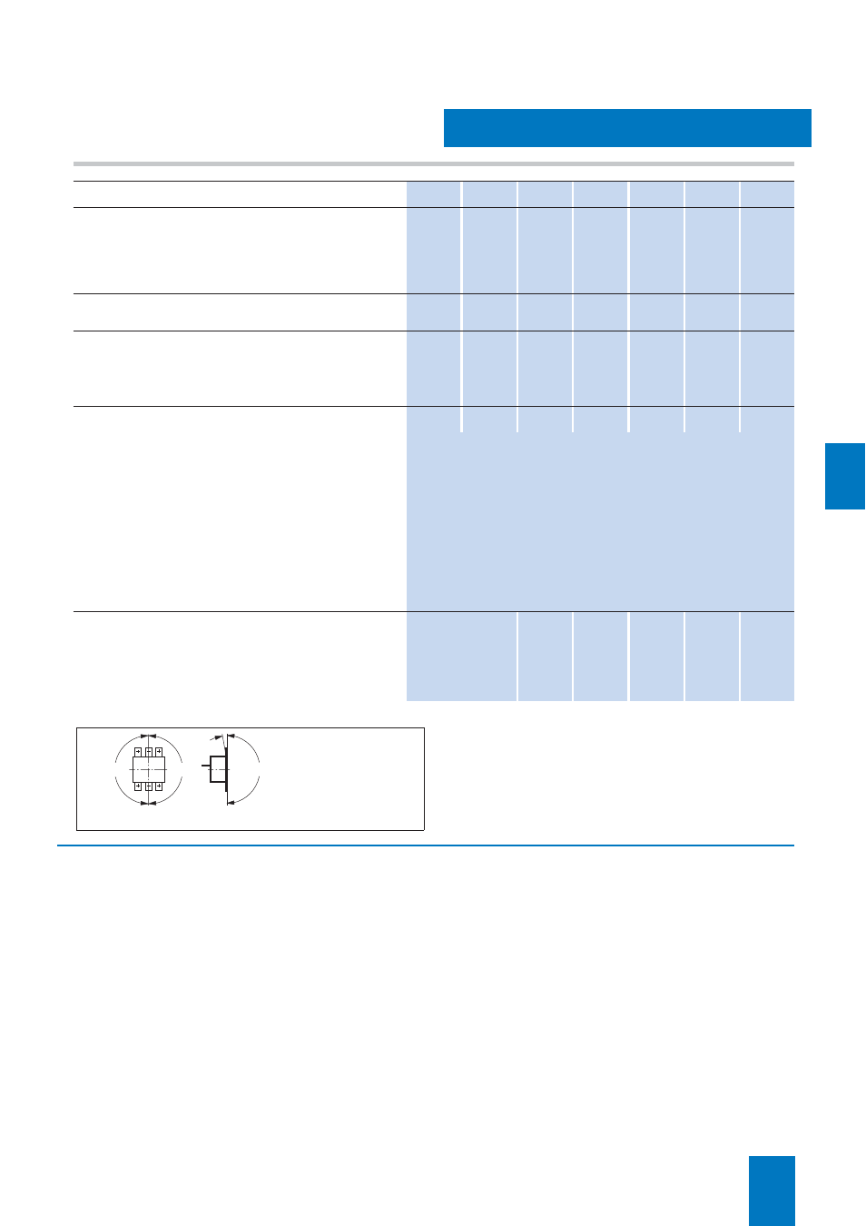
Permissible mounting position
3KL, 3KM
10°
NSE00182
180°
180°
180°