Spectrum Brands MI.20xx User Manual
Page 56
56
MI.20xx Manual
Internally generated sample rate
Clock generation
Termination of the clock input
If the external connector is used as an input, either for feeding in an external reference clock or for external clocking you can enable a 50
Ohm termination on the board. If the termination is disabled, the impedance is 1 Megaohm. Please make sure that your source is capable
of driving that current and that it still fulfills the clock input specification as given in teh technical data section.
Minimum external sample rate
The minimum external sample rate is limited on all boards to 1 MHz and the maximum sample rate depends on the specific type of board.
The maximum sample rates for your type of board are shown in the tables below.
Maximum external samplerate in MS/s
An external sample rate above the mentioned maximum can cause damage to the board.
Ranges for external sample rate
Due to the internal structure of the board it is essential to know for the driver in which clock range the external clock is operating. The external
range register must be set according to the clock that is fed in externally.
The range must not be left by more than 5 % when the board is running. Remember that the ranges depend
on the activated channels as well, so a different board setup for external clocking must always include the
related clock ranges.
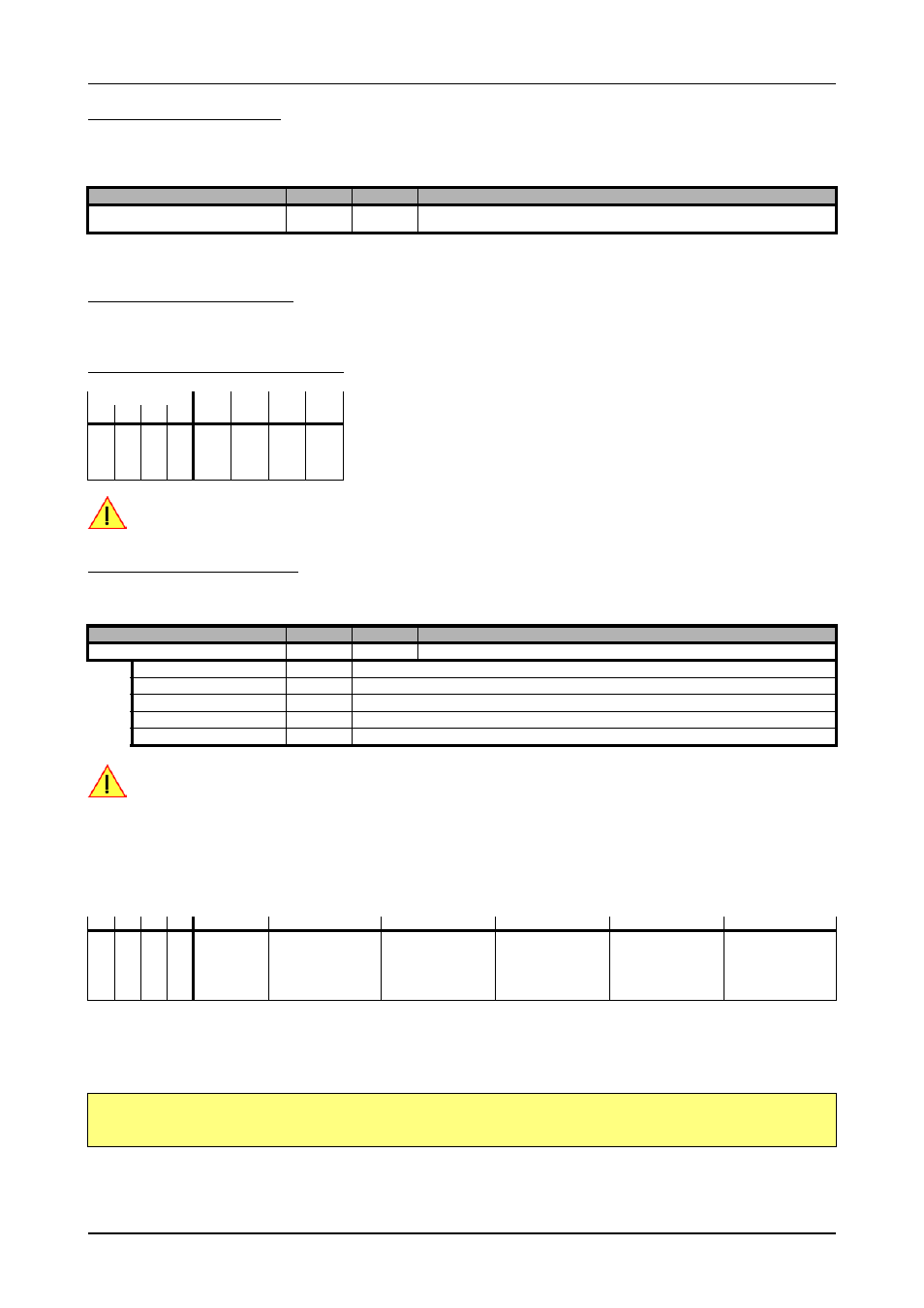
This table below shows the ranges that are defined by the different range registers mentioned above. The range depends on the activated
channels and the mode the board is used in. Please be sure to select the correct range. Otherwise it is possible that the board will not run
properly.
How to read this table? If you have activated all four channels and are using the board in FIFO mode and your external clock is known to
be around 5 MHz you have to set the EXRANGE_BURST_S for the external range.
Example:
Register
Value
Direction
Description
SPC_CLOCK50OHM
20120
r/w
A „1“ enables the 50 Ohm termination at the external clock connector. Only possible, when using
the external connector as an input.
Remapped channels
20
20
20
21
20
30
20
31
ch0
ch1
ch2
ch3
x
50
50
100
100
x
x
50
50
100
100
x
x
n.a.
50
n.a.
100
x
x
x
x
n.a.
50
n.a.
100
Register
Value
Direction
Description
SPC_EXTERNRANGE
20130
r/w
Defines the range of the actual fed in external clock. Use one of the below mentioned ranges
EXRANGE_SINGLE
2
External Range Single
EXRANGE_BURST_S
4
External Range Burst S
EXRANGE_BURST_M
8
External Range Burst M
EXRANGE_BURST_L
16
External Range Burst X
EXRANGE_BURST_XL
32
External Range Burst XL
ch0
ch1
ch2
ch3
Mode
EXRANGE_SINGLE
EXRANGE_BURST_S
EXRANGE_BURST_M
EXRANGE_BURST_L
EXRANGE_BURST_XL
X
Standard/FIFO
< 10 MHz
10 MHz up to max
X
X
Standard/FIFO
< 5 MHz
5 MHz up to max
X
X
Standard/FIFO
< 10 MHz
10 MHz up to max
X
X
X
X
Standard only
< 5 MHz
5 MHz up to max
X
X
X
X
FIFO
< 2.5 MHz
2.5 MHz up to 7.5 MHz
7.5 MHz up to 17.5 MHz 17.5 MHz up to 36 MHz
> 36 MHz
SpcSetParam (hDrv, SPC_CHENABLE, CHANNEL0 | CHANNEL1 | CHANNEL2 | CHANNEL3); // activate all 4 channels
SpcSetParam (hDrv, SPC_EXTERNALCLOCK, 1); // activate external clock
SpcSetParam (hDrv, SPC_EXTERNRANGE, EXRANGE_BURST_M); // set external range to Burst M