Appendix, Appendix a: serial interface, A-1. connectors and signals – Star Micronics SP200F User Manual
Page 90: Rs-232c
– 87 –
APPENDIX
Appendix A: Serial Interface
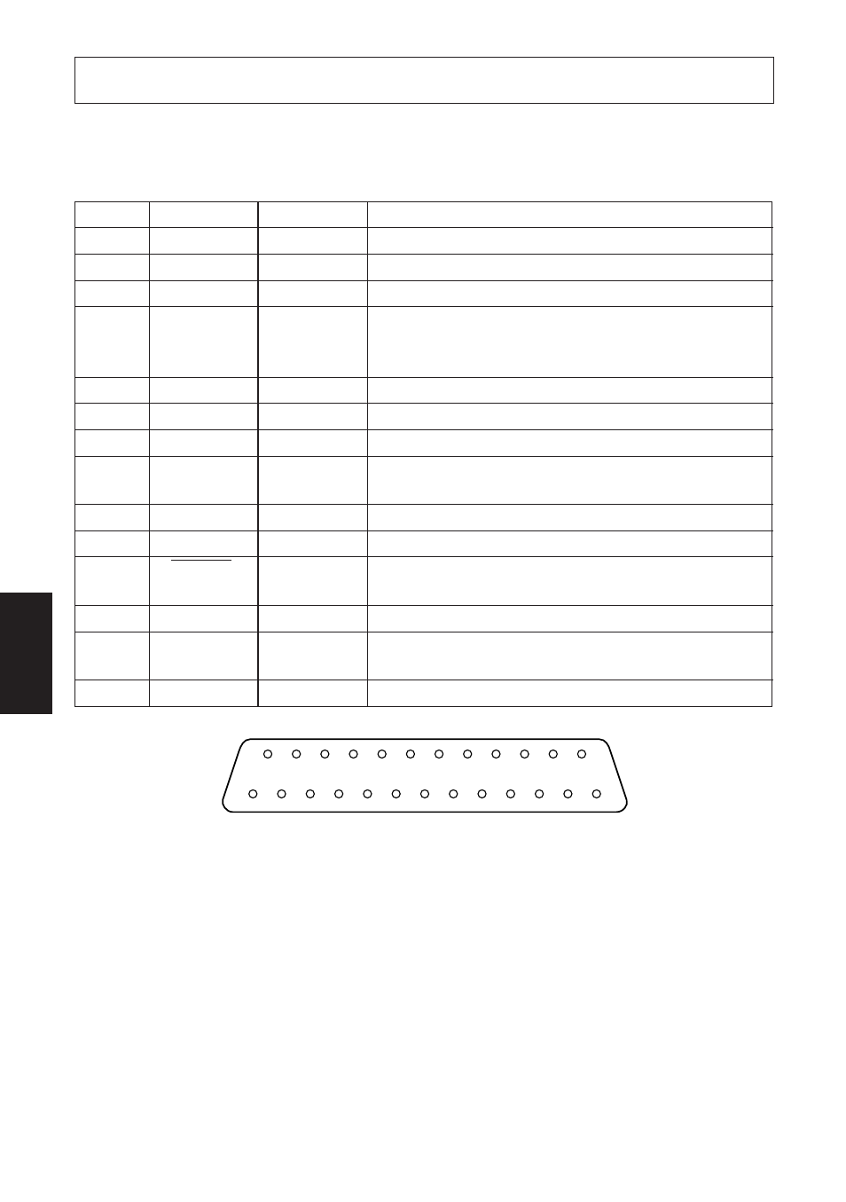
14
1
13
25
A-1. Connectors and Signals
RS-232C
Pin no.
Signal name
I/O direction
Function
1
F-GND
—
Frame ground
2
N/C
Not connected
3
RXD
IN
Received data
4
RTS
OUT
Data transmission request signal. This is always
“SPACE” when the printer is turned on. (Always
“SPACE” status)
5-6
N/C
Not connected
7
S-GND
—
Signal ground
8-10
N/C
Not connected
11
RCH
OUT
When the printer is ready to receive data, the signal line
is same as pin 20.
12
N/C
Not connected
13
GND
—
Signal ground
14
FAULT
OUT
When printer error occurs (such as paper out, mechani-
cal error, etc.) this signal changes to “MARK”.
15-19
N/C
Not connected
20
DTR
OUT
Data terminal ready signal. When the printer is ready to
receive data, this signal changes to “SPACE”.
21-25
N/C
Not connected
Fig. A-1 Serial interface connector
- LC-90 (131 pages)
- LC-240C (82 pages)
- MP500 Series (2 pages)
- Star SP317 (63 pages)
- NL-10 (35 pages)
- MP115MP-24G-A (42 pages)
- LC-6211 (60 pages)
- 800C (76 pages)
- SLIP SP298 (79 pages)
- LC-1021 (91 pages)
- SP200F SERIES (90 pages)
- SP200F SERIES (114 pages)
- 150 (151 pages)
- LC-1011C (88 pages)
- RS232 (80 pages)
- FUTUREPRINT TSP100 (32 pages)
- SP700 Series (2 pages)
- DP8340RC (40 pages)
- SP342F-A (62 pages)
- PR921-24-A (31 pages)
- SP312F (36 pages)
- SP300 Series (70 pages)
- SP317 (63 pages)
- SP2000 Series (147 pages)
- LC-8021 (86 pages)
- NP-325 (45 pages)
- DP8340 (59 pages)
- PW2000-24 (4 pages)
- HL 80825321 (176 pages)
- Line Thermal Printer (181 pages)
- PUNKT-MATRIX-DRUCKER LC-7211 (182 pages)
- Automatic Sheet Feeder SF-15HA (42 pages)
- Star futurePRNT TSP100GT (2 pages)
- Star SP200 Series (127 pages)
- PT-10Q (36 pages)
- SP298 Series (144 pages)
- LC-8521 (116 pages)
- RSR 28 (5 pages)
- SP320S (94 pages)
- Dot Impact Printer (104 pages)
- LC-4521 (191 pages)
- PT-10Y (32 pages)
- Line Thermal/Dot Printer (209 pages)
- ATAR LC-500 (72 pages)