Contents of remote controller switch alarm display – Sanyo AHX0752 User Manual
Page 65
3-3
Trouble Diagnosis
1
2
3
4
5
6
7
8
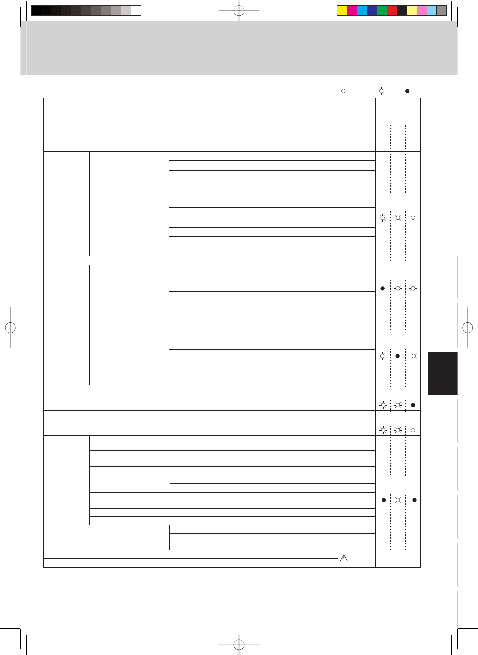
1. Contents of Remote Controller Switch Alarm Display
Overload current detected.
Outdoor unit
Lock current detected.
No current detected when
compressor was ON.
Discharge temp. sensor
trouble
Outdoor unit protection
Outdoor unit protection
Connection failure of oil detection sensor
Fusing of electromagnetic contact (Current detected when compressor was OFF)
Automatic backup operation
<< >> alarm indication: Does not affect the operation of other indoor units.
< > alarm indication: In some cases may affect the operation of other indoor units.
Protective
device
Protective
device
Thermistor
fault
Compressor 2 (constant speed)
Compressor 3 (constant speed)
Compressor 2 (constant speed)
Failure of nonvolatile memory IC (EEPROM) on indoor unit control PCB
Failure of nonvolatile memory IC (EEPROM) on outdoor unit control PCB
<
<
<
F29
F31
H11
H21
H12
H22
H03
H13
H23
H31
H15
H25
H06
H08
(No display changes)
H27
H28
only blinking
Indoor unit
P05
Reverse phase (missing phase) detected.
P16
DCCT, ACCT overcurrent (compressor less than 80 Hz)
P17
P18
P22
P26
P29
Compressor 2 (constant speed) discharge temp. trouble
P14
O2 sensor activated
<
Fan inverter protection function activated.
Float switch is activated.
Thermal protector in indoor unit fan motor is activated.
P03
Compressor 1 (INV) discharge temp. trouble
P04
F04
F05
F22
F12
F16
F17
F24
F23
F08
F07
F06
High-pressure switch
Compressor 1 (INV) discharge temp. senso r
Compressor 2 (constant speed) discharge temp. senso r
Compressor 3 (constant speed) discharge temp. senso r
Outdoor air temp. senso r
Heat exchanger 1 liquid temp. senso r
Heat exchanger 1 gas temp. senso r
Compressor intake temp. sensor (suction temp)
High-pressure sensor
Low-pressure sensor
Heat exchanger 2 liquid temp. senso r
Heat exchanger 2 gas temp. senso r
Compressor 3 (constant speed) discharge temp. trouble
Outdoor unit fan trouble
DCCT, ACCT overcurrent (80 Hz or more)
Start failure caused by compressor wire missing phase, DCCT
failure, or similar problem (INV compressor start failure).
Outdoor unit
Compressor 3 (constant speed)
Compressor 1 (INV)
Compressor 2 (constant speed)
Compressor 3 (constant speed)
Low-pressure trouble
Compressor 2 (constant speed)
Compressor 1 (INV)
Compressor 2 (constant speed)
Compressor 3 (constant speed)
HIC trouble alarm
Compressor 3 (constant speed)
Ceiling panel connection failure
Operating and timer
lamps blinking
alternately
Timer and heat
ready lamp blinking
alternately
Operating and heat
ready lamp blinking
alternately
Timer lamp blinking
Operating and timer
lamp blinking
simultaneously
Operating and timer
lamp blinking
simultaneously
Wired
remote
control
display
Wireless
remote controller
receiver display
ON:
Operation
T
imer
Standb
y
for heating
Blinking:
OFF:
Possible cause of malfunction