Sanyo AHX0752 User Manual
Page 59
2-39
1
2
3
4
5
6
7
8
1
2
3
4
5
6
7
8
Remote Control Functions
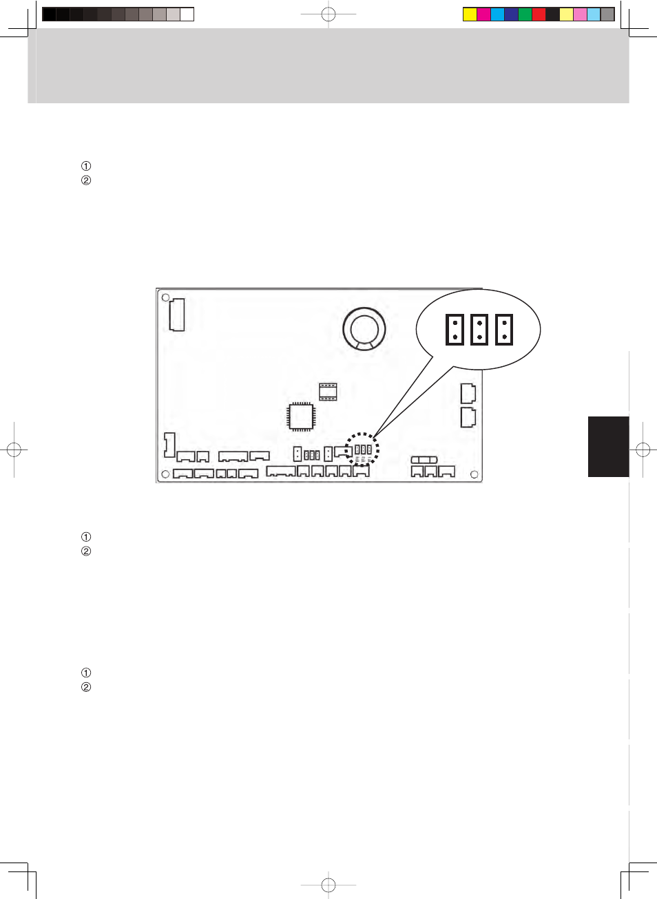
Selecting the DC fan motor tap (when setting from the PCB)
●
4-way Air Discharge Semi-Concealed type
Open the electrical component box cover, then check the indoor unit control PCB.
Connect the jumper connector (2P: yellow) which was supplied with the accessory to the correct connector pin
on the indoor unit control PCB according to the setting number which was confirmed in Table 1 (Table of DC
Fan Motor Tap Settings).
• If the setting No. is (1), then connect the jumper connector to the connector pin TP1 (2P: red) on the indoor unit
control PCB.
• If the setting No. is (3), then connect the jumper connector to the connector pin TP3 (2P: yellow) on the indoor unit
control PCB.
●
Suspended type
Open the electrical component box cover, then check the indoor unit control PCB.
Connect the jumper connector (2P: yellow) which was supplied with the accessory to the correct connector pin
on the indoor unit control PCB according to the setting number which was confirmed in Table 2 (Table of DC
Fan Motor Tap Settings).
• If the setting No. is (1), then connect the jumper connector to the connector pin TP1 (2P: red) on the indoor unit
control PCB.
• If the setting No. is (3), then connect the jumper connector to the connector pin TP3 (2P: yellow) on the indoor unit
control PCB.
●
1-way Air Discharge Semi-Concealed type
Open the electrical component box cover, then check the indoor unit control PCB.
Connect the jumper connector (2P: yellow) which was supplied with the accessory to the correct connector pin
on the indoor unit control PCB according to the setting number which was confirmed in Table 3 (Table of DC
Fan Motor Tap Settings).
• If the setting No. is (1), then connect the jumper connector to the connector pin TP1 (2P: red) on the indoor unit
control PCB.
• If the setting No. is (3), then connect the jumper connector to the connector pin TP3 (2P: yellow) on the indoor unit
control PCB.
3. Timer Remote Controller (RCS-TM80BG)
TP6
White Yellow Red
TP3 TP1