Shure LX88-II User Manual
Page 5
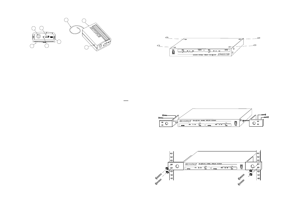
LX1 Body-Pack Transmitter Features & Controls (Figure 3)
Б
ББББ
ББББ
ББББ
ББББ
ББББ
ББББ
ББББ
Б
БББ
БББ
БББ
БББ
БББ
БББ
БББ
БББ
БББ
БББ
БББ
БББ
БББ
БББ
БББ
БББ
БББ
БББ
БББ
БББ
ББББ
ББББ
ББББ
ББББ
Б
Б
Б
Б
Б
Б
Б
Б
Б
Б
БББ
БББ
БББ
Б
БББ
БББ
БББ
БББ
ББББ
ББББ
ББББ
Б
Б
Б
БББ
БББ
БББ
БББ
БББ
Б
Б
ББББ
ББББ
ББББ
БББББ
Б
БББ
БББ
БББ
БББ
LX1 BODY-PACK TRANSMITTER FEATURES & CONTROLS
FIGURE 3
ББ
ББ
Б
Б
Б
Б
Б
Б
Б
Б
Б
Б
Б
Б
Б
Б
Б
Б
Б
Б
Б
ББ
Б
Б
Б
Б
ББ
Б
Б
Б
Б
Б
Б
Б
Б
ББ
Б
Б
Б
Б
Б
Б
Б
Б
БББ
БББ
ББ
Б
ББ
Б
Б
ББББ
ББББ
ББББ
ББББ
Б
Б
ББ
Б
Б
Б
Б
Б
Б
Б
ББ
ББ
Б
ББ
ББ
Б
Б
Б
Б
Б
Б
Б
Б
Б
Б
Б
Б
Б
Б
Б
Б
Б
ББ
ББ
ББ
Б
Б
Б
Б
Б
ББ
Б
ББ
Б
Б
ББ
ББ
Б
Б
Б
Б
Б
Б
БББ
БББ
БББ
БББ
8
7
6
Б
Б
Б
Б
Б
Б
Б
Б
Б
Б
Б
Б
ББББ
ON
MUTE BAT OFF PWR
Б
Б
Б
Б
Б
Б
Б
Б
ББ
ББ
ББ
ББ
Б
Б
ББ
Б
Б
Б
Б
Б
Б
Б
Б
Б
Б
Б
Б
Б
Б
Б
Б
Б
ББ
Б
ББ
Б
Б
Б
Б
ББ
Б
ББ
ББ
Б
Б
Б
Б
ББББ
Б
Б
ББ
Б
Б
1
2
4
3
5
1. POWER ON/OFF Switch.
2. Power/Battery Fuel Gauge. Indicates the power level of the battery.
3. Input Jack. Tini “Q-G” input connector for microphones or instruments.
4. Mic On/Mute Switch. “Mutes” the transmitter to prevent unwanted sounds
from being picked up by the receiver
without turning the transmitter off.
5. Belt Clip. Secures Body-Pack to clothing or guitar strap.
6. Antenna. For best operation, the antenna must hang vertically, it should not
be coiled or bundled.
7. Audio Gain Control. Provides audio level adjustment to accommodate dif-
ferent sound sources.
8. Battery Compartment. Access to the battery.
SYSTEM INSTALLATION
MOUNTING THE RECEIVER
The LX88-
II
Dual Channel Wireless Receiver can be mounted in two ways: as a
stand-alone unit or as a rack-mount unit.
As a Stand-Alone Unit (Figure 4)
INSTALLING RUBBER FEET
FIGURE 4
1. Turn the unit upside-down.
2. Place the rubber feet supplied with the package in the four corners of the base.
3. Turn the unit rightside-up. It can now be mounted on any flat surface, such as a
table, with the feet working as anchors to prevent slipping.
As a Rack-Mount Unit
1. Remove the two screws from each side of the receiver.
2. Position the mounting brackets over the holes on the sides of the receiver
and secure to the receiver with the screws from Step 1 (Figure 5).
RACK–MOUNTED RECEIVER
FIGURE 5
ББ
ББ
ББ
БББ
БББ
ББ
ББББ
ББББ
3. Secure the assembly to a standard audio equipment rack with four screws
(Figure 6).
INSTALLING RECEIVER IN A RACK
FIGURE 6
Б
Б
Б
Б
БББ
БББ
ББББ
ББББ
ББ
ББ
ББББ
ББББ
4
5