4 mechanical overview, Mechanical overview, Figure 1: enclosure drawing – SSI America ERP2U User Manual
Page 9
SSI
ERP2U Power Supply Design Guide, V2.31
- 9 -
4
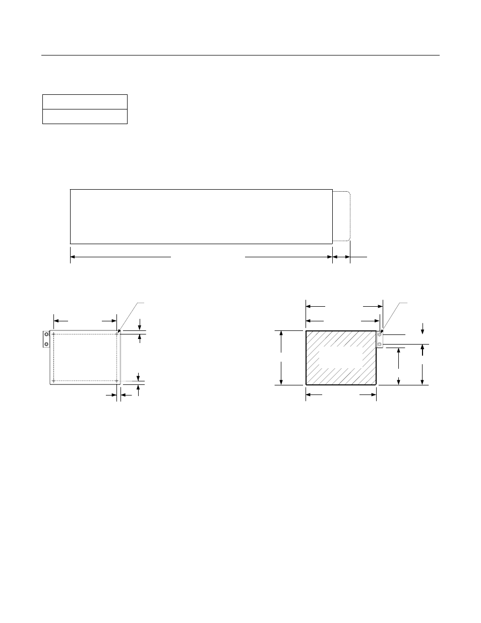
Mechanical Overview
STATUS
Required (Optional)
The ERP2U is a power sub-system made up of a cage and redundant, hot swappable power supply modules. A
mechanical drawing of the cage is shown below in Figure 1. Two depths are defined to the cage; 400mm and
350mm. This cage is intended to be mounted in the system and not redundant or hot swappable. The exterior
face of the cage accepts hot swappable power supply modules. The cage distributes output power from the
modules to a wire harness. Cooling fans, EMI filtering, and IEC inlet connector(s) may be located in the modules
or cage.
400.0 +/- 1.0
400.0 / 350.0 +/-1.0
30 MAX
HANDLE/LATCH
Figure 1: Enclosure Drawing
108.0 +/- 0.5
113.0 +/- 0.5
118.0 +/- 1.0
61.8 +/- 0.5
15.0 +/- 0.5
83.0 +/- 0.5
56.8 +/- 1.0
#6-32 THD
2 PLACES
6.0 +/- 0.5
6.0 +/- 0.5
6.0 +/- 0.5
96.0 +/- 0.5
#6-32 THD
4 PLACES
MODULE
ACCESS
FRONT VIEW
REAR VIEW
SIDE VIEW