6 dc output specification, 1 output connectors, 1 required baseboard power connector – SSI America ERP2U User Manual
Page 15: Dc output specification, Output connectors, Required baseboard power connector, Table 8: p1 baseboard power connector, Table 9: processor power connector
SSI
ERP2U Power Supply Design Guide, V2.31
- 15 -
6
DC Output Specification
These are the output requirements for the power supply assembly including cage and module.
6.1 Output
Connectors
The power supply distribution board shall have one of the two following output connector and wire harness
configurations, depending upon the type of 12V rail configuration needed by the system.
6.1.1
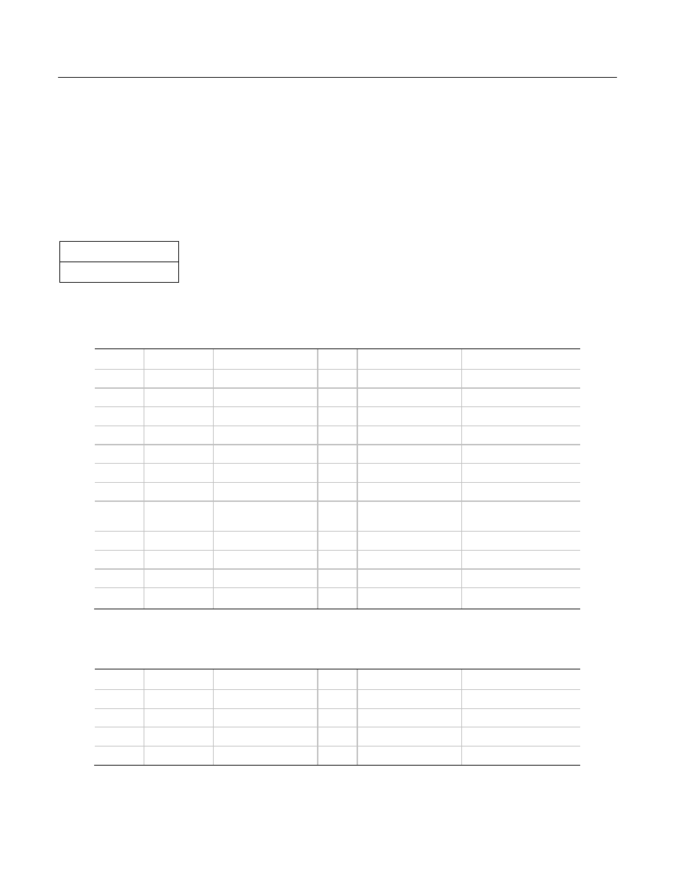
Required Baseboard power connector
STATUS
Required
Connector housing: 24-Pin Molex
39-01-2240 or equivalent
Contact: Molex
44476-1111 or equivalent
Table 7: P1 Baseboard Power Connector
Pin
Signal
18 AWG Color
Pin
Signal
18 AWG Color
1
+3.3 VDC
Orange
13
+3.3 VDC
Orange
2
+3.3 VDC
Orange
14
-12 VDC
Blue
3 COM Black
15
COM
Black
4 +5
VDC
Red
16
PS_ON
Green
5 COM Black
17
COM
Black
6 +5
VDC
Red
18
COM
Black
7 COM Black
19
COM
Black
8
PWR OK
Gray
20
Reserved (-5 V in
ATX)
N.C.
9
5 VSB
Purple
21
+5 VDC
Red
10
+12 V3
Yellow
22
+5 VDC
Red
11
+12 V3
Yellow
23
+5 VDC
Red
12 +3.3
VDC
Orange
24
COM
Black
If 240VA limiting is not a requirement for the power supply than all +12V outputs are common and may have the same wire
color (yellow).
Table 8: Processor Power Connector
Pin
Signal
18 AWG color
Pin
Signal
18 AWG Color
1
COM
Black
5
+12 V1
Yellow/Black Stripe
2
COM
Black
6
+12 V1
Yellow/Black Stripe
3 COM Black
7
+12
V2
Yellow
4 COM Black
8
+12
V2
Yellow