5 field replacement unit (fru) signals, 1 module fru data, 2 module fru data format – SSI America ERP2U User Manual
Page 32: 1 product info area, Field replacement unit (fru) signals, Module fru data, Module fru data format, Table 32: fru device information, Table 33: fru device product information area
SSI
ERP2U Power Supply Design Guide, V2.31
- 32 -
PDB
addressing
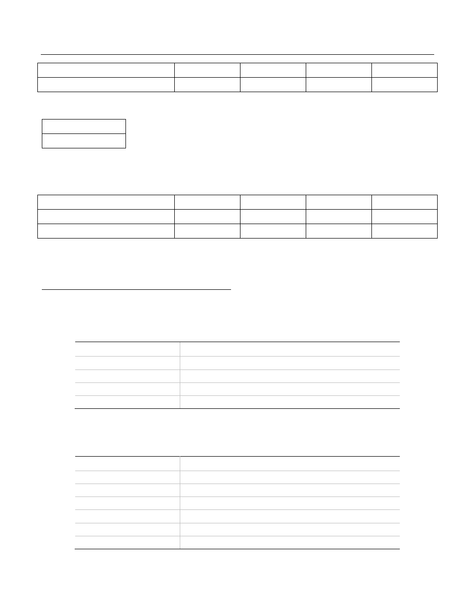
A0/A1 0/0 0/1 1/0 1/1
Power supply PSMI device
B0h
B2h
B4h
B6h
8.5 Field Replacement Unit (FRU) Signals
STATUS
Optional
The FRU device in the power supply shall derive its power off of the 5VSB output on the system side of the or’ing
device and grounded to ReturnS. The Write Control (or Write protect) pin should be tied to ReturnS inside the
power supply so that information can be written to the EEPROM.
PDB
addressing
A0/A1 0/0 0/1 1/0 1/1
Power supply IPMI FRU device
A0h
A2h
A4h
A6h
Power supply PSMI device
B0h
B2h
B4h
B6h
8.5.1
Module FRU Data
FRU data shall be stored starting in address location 8000h through 80FFh. The FRU data format shall be
compliant with the IPMI specifications. The current versions of these specifications are available at:
http:\\developer.intel.com/design/servers/ipmi/spec.htm.
8.5.2
Module FRU Data Format
The information to be contained in the FRU device is shown in the following table.
Table 31: FRU Device Information
Area Type
Description
Common Header
As defined by the FRU document
Internal Use Area
Not required, do not reserve
Chassis Info Area
Not applicable, do not reserve
Board Info Area
Not applicable, do not reserve
8.5.2.1 Product Info Area
Implement as defined by the IPMI FRU document. Product information shall be defined as follows:
Table 32: FRU Device Product Information Area
Field Name
Field Description
Manufacturer Name
{Formal name of manufacturer}
Product Name
{Manufacturer’s model number}
Product part/model number
Customer part number
Product Version
Customer current revision
Product Serial Number
{Defined at time of manufacture}
Asset Tag
{Not used, code is zero length byte}